Tutorial: Modelling for Goldsource with Gmax Last edited 3 months ago2024-09-23 01:04:51 UTC
Modelling for Goldsource
Part 1
Introduction:First off, you must have the necessary tools. This tutorial teaches how to accomplish a modeled asset with 3D Studio Max for Half-Life 1, even though there are other programs you can use to model, they are all a bit similar. If you do not wish to pay for Max, there is GMax available for free. The tools are the same with minor differences, without the advanced high-end rendering engines and third party plugins.
Gmax is available here, but unfortunately the registration service has died a long time ago, a workaround (not supplied) may be required. An SMD plugin is available here.
For those with the full blown 3DS Max, there are tools available here.
The necessary tools for this tutorial are:
- Max or Gmax
- Studio Model Compiler or the GUI version
- The necessary plugins
- A Half-Life .mdl file viewer
The plugins go in the plugins folder in the Max directory.
Example: c:/3dsmax7/plugins/
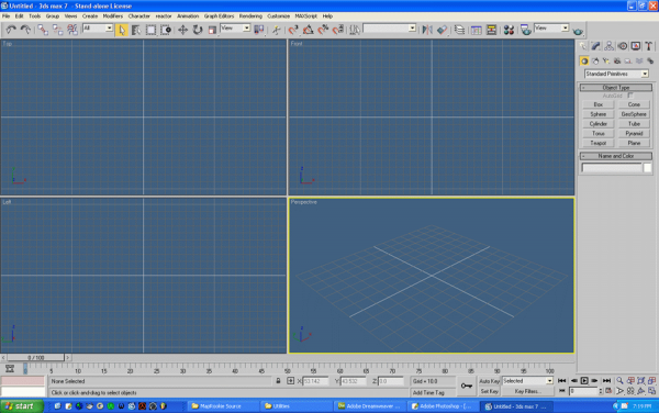
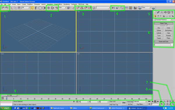
Once setup is done. Open Max you should see this. You should see the typical 4 views in various dimensions for you to work with. You have a perspective views, top, left, front, and a grid on each.
NOTICE: Max's grid is not like that of Hammer if you have experience with that. By default, its set in 10 unit increments, might even be set in inches or centimeters if this is your first time.
So we need to adjust the grid so that it mimics the proportions in Hammer. Once you set this and save a max file, this setup stays with the Max file, but if you start new, the grid resets to 10 increments and the viewports even switch to default if you have changed them to look like Hammer as well.
Comfort and familiarity is your best weapon against Max's mega complexed interface. Most of which you will not use. I normally set it up like Hammer, and I choose my favorite color for the background (and apparently the whole website).
To setup the viewports, you can Right Click on the view label in the upper left corner to get some options. You will see the different render levels like Smooth + Highlights, Flat, Wireframe, and so on. Select Views and more options will appear for you to choose from.
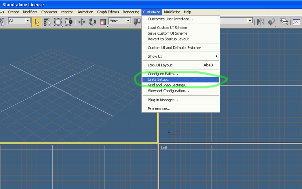
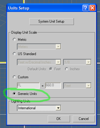
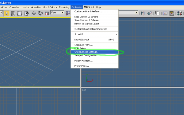
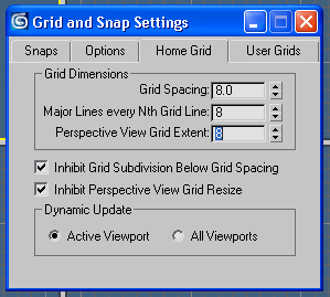
Next is to change the grid. On the menu bar, go to Customize > Units Setup... A dialog will appear, choose Generic Units. This is the same type thats in Hammer and the Same proportions HL uses. Change the grid increments by going to Cusomize > Grid and Snap Settings... You'll get another dialog window, select the Home Grid tab and type 8 for the three values. The Grid will automatically update, when you close this window, you will be all set for modelling. Here is a crash course for the interface
1: Undo and Redo, also the standard CTRL+Z and CTRL+Y
2: Move, Rotate, and Scale. With a selection of almost any type, you can manipulate them with these.
3: Your Grid Snaps! The first one is to the grid itself. The Second is to rotated in units of 5 for more precise rotation without decimals. The third is like the second only its for Scaling in units of 10, and the last one deals with parameter spinners staying only on whole numbers without decimals.
4: Your basic flip and align. Useful for many things.
NOTICE: My version of the export plugins are faulty. When you flip any part of an object and export it to HL, the faces of the flipped parts will be inverted. There is an easy and much better way of flipping the object rather than the flip option. It is called the Symmetry Modifier.
5: The Main Tools. Everything you need is right here. The top row of tabs are sets, which include Create, Modify, Hierarchy, Motion, Display, and Utilities. The second row only appears when the Create tab is selected. The second row consists of things you can make like geometry, lights, cameras, shapes, and so on.
6: Parameters, under create and geometry, you get a series of primitives, you'll place and manipulate these to make your model, whatever it may be. Also, when on diferent tabs, this area changes to provide parameters and options for whatever tab or object your have selected.
7: Maximize viewport, for preference, you can expand the selected viewport. The selected view is the one with the yellow outline bordering it. I'm noting this so if you need it when modelling or previewing.
8: Time Configuration, for animating your model. This is often missed and its a very important and small button. I'll recap this later when needed.
9: Time Line, you can place keyframes of animation here for your model. Its easy to work with and as simple as drag and drop.
Thats a run down, anything more detailed than that will be noted in the lesson.
NOTICE: I recommend you take the time now to click through and explore the geometry, shapes, parameters, modifiers, and so on. But please be careful when doing so, even with my advanced experience, I still manage to crash Max and corrupt my files. Along the way, I will tell you what to do and what not to do to prevent any of this.
Here is the best advice I can give you right now. Max is only as complicated as you make it. It is not a heavy graphics program until you make it one. The polygon count starts at zero and increases with every object you place, and with every object, everything about them and their properties.. This software is not a child's toy and must be used with precautions about your computer's limits and the program's limits. If you have a video card capable of it, set it to performance mode for Max, its power will be much more needed rather than its prettiness. Max doesn't give a damn if the lines are antialiased.
Ultimately, Max has several engines, coinciding with either Direct3D or OpenGL, I use OpenGL because its the higher performance engine versus D3D. Also, Max has a preview engine and a render engine. Things will look so outrageously more pretty when you render rather than what your see in your viewports. The difference, the viewports must be real-time for editing, and rendering can take minutes, sometimes hours to make 1 frame. You can use the occasional render to see how your model really looks, and in fact, you can change the render settings to mimic that of HL, or even HL in software mode. You have full control over this massively powerful engine.
Understand the beast before you tame it. So lets tame it already. Make it our b!tch.

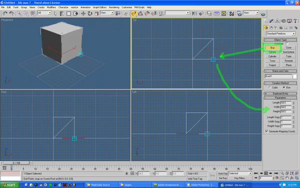
Overcome all that fear and click the box tool under create. On your top view, drag out a 64 x 64 square. You can turn on you grid snap to help with this. When you drag up, you can define a height, it too should be 64 units. If at all you mess this up, you can type it in manually and change its dimensions on the right side in the parameters. Now that you have something, you can rotate around it by holding ALT and Middle clicking on the Perspective view. Also, middle click is the pan hand tool shortcut, you can use this on any window. Zooming is the Mousewheel itself, or CTRL+ALT+Middle Click then forward or backward with the mouse. Alternatives are at the bottom right hand of the screen near the maximize and time configuration buttons. Go ahead and observe your box in 3D.
...
Ok! Let me start by saying you have officially modeled something by making this box. You have taken a step much farther than most can even comprehend. If you've done this before, you have no idea what you've done likely. So lets make our box into something you didn't realize it could be.
Lets make a CRATE! Didn't see that coming now did ya? Woooo.
Instead of a bland flat-faced crate, we have the power of modeling. So lets make one that looks nice, in fact we'll make it sexy.
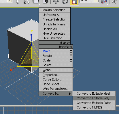
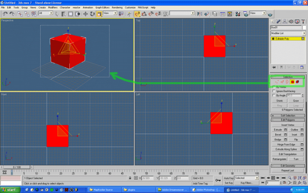
Select your object if its not already, right click on it and you get a mini menu. If it didn't show up the first time, keep right clicking, Max can be sticky with this menu. You can use this to shortcut some tools, and I thinks its customizable, though I've never messed with it. Its biggest advantage is that you can quickly make an object into something we can actually use. Select Convert To and choose Editable Poly. You will open up a lot of options to manipulate your box on the right side. This is the modeling playground of Max in other words. Select the Face Selection and drag a box over the whole thing on any of you views, every face will be selected. Now, crates have a nice trim along all of the edges, so with our selection, we'll make that.
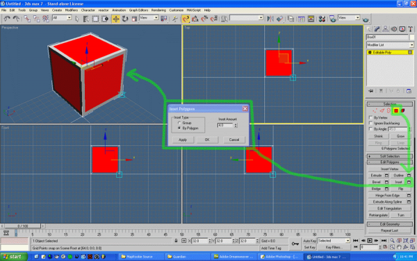
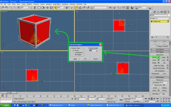
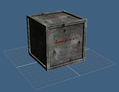
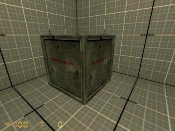
Scroll down on your parameters until you see the Inset button. Select the box just to the right of it with the window icon. This will open a dialog for numeric input options rather than click and drag. You can do that, but it won't be accurate when it comes to texturing. So open it, under Type, click By Polygon, and type 4 for the value. You'll see your select shrinking inwards. So now you get that nice frame, but the inside part is level with the rest of it. Click the Extrude's settings button and type -2 in the value. This will pull the selected faces in by that many units. HUZZAAAAAH! An untextured crate!
Texturing is easy once you figure out how it works. Its not like Hammer because Hammer doesn't offer dozens of shaders, bumps maps, normal maps, specularity, glossiness, raytrace reflection and refraction, and a wealth of other shaders you have probably never heard of that you'll eventually use in the advanced tutorials.
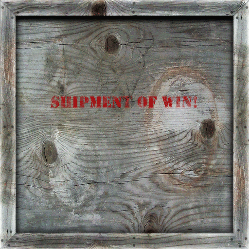
Download the following image. Place it in a folder located anywhere, give the folder a name like myfirstcrate or something. This will be your project folder. Anything and everything involving this model will go there. Also, open it in MSPaint or Photoshop and change it to a 8bit BMP file and resave. HL models only read that format, but Max can read any format out there, at any resolution and size. It doesn't need to be in powers of 2. It can even use and play video files like AVIs, MPGs, and Quicktime MOVs. I sh!t you not, Max is powerful with its shader networks. After you nab that freebie, press M to open the material editor. You get a bunch of sample spheres that are in a window you can scroll up and down, left and right. Just saying that because you have more than 6. Right click on a sphere and select 6 x 4 sample windows. It'll display them all if you choose to.
Select any one of them.
In its parameters below, scroll down until you see the Maps rollout. Open it if it isn't already. Here is a summary of all of the maps you can pump into this primitive Standard Blinn shader based material. This is the kiddie stuff.

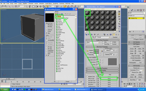
Click the NONE right of the Diffuse slot. Diffuse is the base texture color format, its what Hammer and HL uses. A window will open and you'll get a long list of Shaders. At the top, click Bitmap. An Open dialog will appear for you to locate the crate texture. Go find it and click OK.
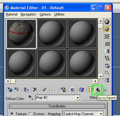
You'll see the sphere change, it has your image applied to it. Click the Go To Parent button to take a step back in the editor. Like a back button in a web browser. This will take you back to the maps rollout and all that fun.
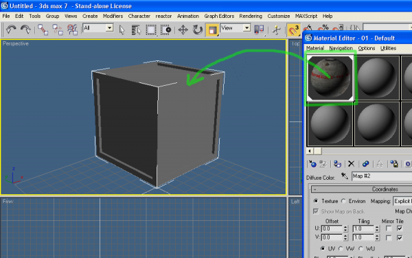
Now lets plop it on our model. Drag the sphere with our texture and drop it on the crate. LOLWUT!?!? Nothing happened.
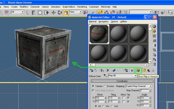
Click this button. That enables the texture map to be viewable in the viewports. When you have loads of shader networks working together with high resolution images, you may see where this is necessary.
Ok... But wait, there's ugliness on the model. Yes. When primitives are initially made, i.e. a box, they start with Mapping Coordinates. These coordinates help apply the texture correctly. Since we Modified our initial box, we messed them up and now they've stretched the same way we stretched parts of the model to make it.
Let fix that texturing. First turn off face selection mode in the object parameters. So now you have the object as a whole rather than its faces.
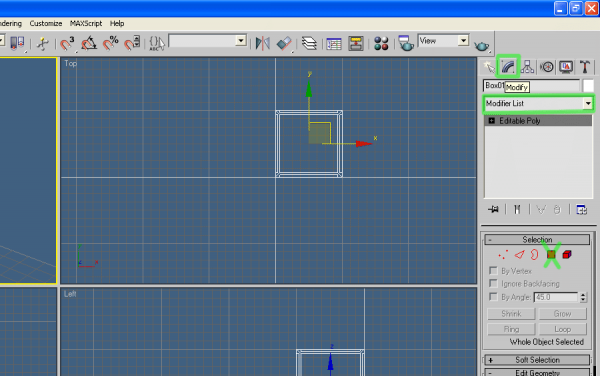
You may not have noticed, but you are on the Modify tab on the right. Next, Select the Modifier List. You'll see a massive list of modifiers that can automatically do large amounts of work for you... just what everyone wants to hear

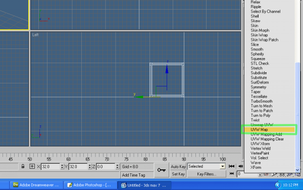
Select UVW Map, near the bottom. This is a modifier to help us reorient the texturing by using some projections.
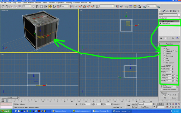
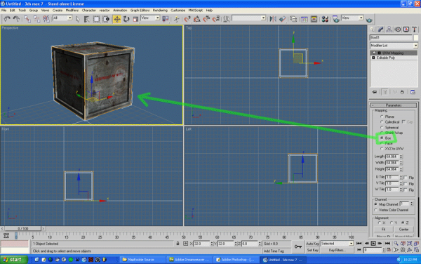
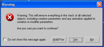
When selected, it goes on top of the Editable Poly in the list under the modifers dropdown. This works like photoshop layers, you can combine and rack up many, many, many modifiers at once. Be careful though, this is hard on Max to calculate all of that. I often collapse my layers to save memory and ram. Also, this is the part that crashes more than anything else. Don't fear it though, just use them kinda sorta wisely. If you are done with it, collapse it. Upon applying it to your model. You'll instantly get a new rollout of options and parameters. Its default is set to Planar, as you can observe an orange plane around your model. It looks perfect on top, but not even close on the sides. Out of the the several projections, select Box beacuse... well... we have a box. WOOT! Its perfect on all sides now, though every side is the same, who cares. It looks good! You can collapse this mapping to your model by selecting the modifier on top of you object in the modifier stack, right clicking, and collapse all. EEEEeeee.... ya ok. Clicking Hold/Yes makes it undoable, Yes it permanant, and no cancels. Click either of the Yes options.
When you do so, you go back down to square one, only polygons and textures but the changes you've made will stay.
Save.
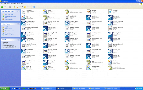
Every model should have its own folder. They get filled with related stuff. Here's an example of one of mine... Yup. It'd be harder to work with if I had multiple modelling projects in there.
Name the Max file something like crate_base or crate_reference.
We could export what we have so far, but there is one problem. It has no bones. If you are aware, HL runs on an advanced boning and animation system. Since its release, our tools have advanced so we have a large advantage now.
Center your sexy crate into the middle of the world, or centered on the small swatch of grid on the perspective view. Its good to make everything centered anyway.
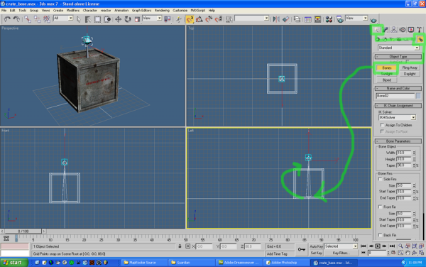
On the Create Tab, select Systems and choose Bones. On your Left or Front view, click once at its base, then click again straight above that, then right click to the line and add an ending stub. Thats a bone. Lets bind our model to it.
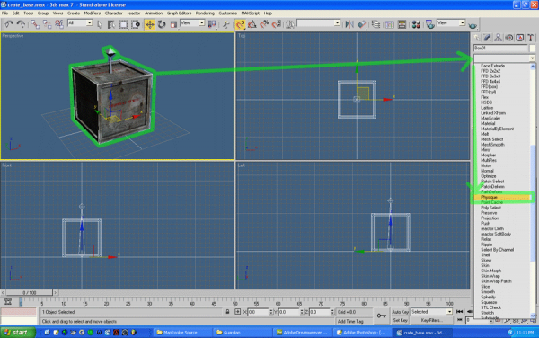
Select your crate and choose from the modifiers list Physique Skin works too, but Physique is more refined and HL was built on it on this powerful system on Max4. Physique will be easier for the n00b and l33t alike when modeling. Plus skin can glitch up your models. I recommend against it.
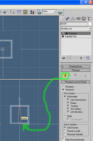
After you've chosen Physique from the list, Click Attach to Node. Then click the bone you want it to initialize from. We only have 2, so click the bottom one. A window will show up with more options about parameters and advanced features. Its a box. It won't do much so click Initialize.
Now when we move the main bone, the crate goes with it. If this was a character, you could very easily change his pose and animate it. But we have a box as of now, so it won't flex, run, or try to eat the player's face.
Now we need to export it.
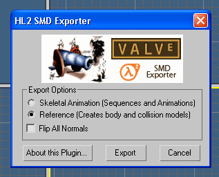
Go to File > Export and browse to your project folder where you're keeping everything. Change the filetype to Valve HL2 SMD. Save it as crate_base.smd. Clicking ok brings up an exporter options window. Either this SMD is an animation or a reference model. Its a reference model so choose that and click Export. You'll get a quick status report and thats it. Since our box does absolutely nothing, click export again and save it again as crate_idle1.smd. This is the animation of it sitting there and doing nothing. Its entirely necessary. Choose Skeletal Animation and export it.
NOTICE: It may be out of habit for some of you to select the other one, sample its name and change the ending to be different, but a glitch upon naming SMDs using this plugin, it will save over the one you clicked. Type the name out from scratch to prevent this glitch from happening. Since your model has its own folder, its valid to just type is "reference" or "idle1" for each of the SMDs. You can call it whatever you want, as long as the HL engine knows what it is.
Exporting is done. It's that simple.
The QC script is a whole new animal. I haven't mastered it, and there is no master guides out there that tell you every detail. The best ones I've found and use often still leave out certain parts because no one know what they are. Either way, we have to have one to compile our crate.
Here is the most basic QC script for an HL1 prop.
$modelname "prop.mdl"
$cd "."
$cdtexture "."
$scale 1.0
$cliptotextures

$bbox 0.000000 0.000000 0.000000 0.000000 0.000000 0.000000
$cbox 0.000000 0.000000 0.000000 0.000000 0.000000 0.000000
$eyeposition 0.000000 0.000000 0.000000
$origin 0 0 0


//reference mesh(es)
$body "studio" "prop_base"


// 1 animation sequence(s)
$sequence "idle1" "prop_idle1" fps 30

// End of QC script.
Copy that and paste it into a notepad document and save it to your project folder as a .qc file. Be sure the file type is All Files. The name does not matter. You may call it whatever you want. If you haven't already, set .qc files to be read via notepad, it will save you some headcakes.
Now we edit the script to fit our model.
Obviously change the modelname at the top to firstcrate.mdl or whatever you like.
Down at $body you should type "crate_base" there instead of prop_base. Leave the "studio" alone. HL won't read you model if you change that.
A few lines lower in $sequence, leave the "idle1" and change the "prop_idle1" to "crate_idle1"
If you use different names other than those, type your names in respectively.
Save it again and thats the basics of QC script.
Install the Model Compiler from the utilities package if you haven not already.
The compiler requires the following:
1: All related files must be in the same folder as the QC script, which should be in your project folder.
2: All of the names must be correct corresponding to the script, and the files must be present at the time of compiling.
3: All textures must be 8bit .BMP files. Nothing else works.
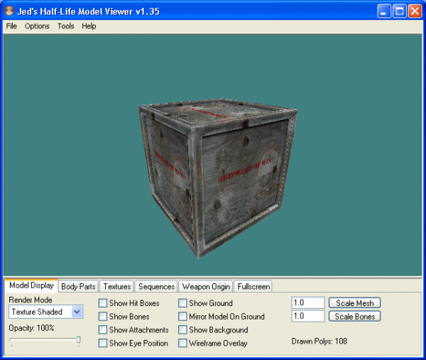
Open the compiler and search for your QC script and compile it. Use File > Load QC File for that. After you loaded it, click compile! A .MDL Half-Life model will appear in your project folder. You can open it in a model viewer and see it yourself. If anything goes wrong, the compiler will tell you what went wrong. If you went by the above criteria, you should not have a problem with this model. You can make the experience even sweeter by loading it into HL itself.
NOTICE: A model viewer can give you an accurate polycount of your model. If working on a model and you are unsure of its count, quickly export it to grab a count so you can budget accordingly. Another way to get an accurate count is to use the Polygon Counter plugin that comes with max. (which was removed in later versions of it, max9 and up)
It can be accessed by selecting the Utilities tab, located near the Create tab on the far right. It has an image of a carpenters hammer on the tab. Click [More] and choose it from the list. Your Shipment of Win has arrived.
Additional Note:
I have found out (by mistake really) that when making prop models, you do not need to give it bones. You can simply use the World's Origin as the model's origin, and each separate object in your model will have a bone point automatically applied to its pivot point. This offers simple but limited animation and can save some time. If it is a character or something not quite as rigid, bones are still needed. This must be a feature of the compiling tools or something, either way, it works without error.
Another Additional Note:
A glossary of QC commands can be found here for more advanced compiling. There are a lot of fragments and unknown commands, but the important stuff works fine and is well documented.
Modelling for Goldsource
Part 2
Introduction:Its a lot to take in all at once, you deserve a break, but if you're ready, lets continue with a shorter lesson on meshing more complicated pieces of geometry together.
So now we are going to make some complicated pipes that would otherwise give Hammer a hard time if we were to make it from Brushes.
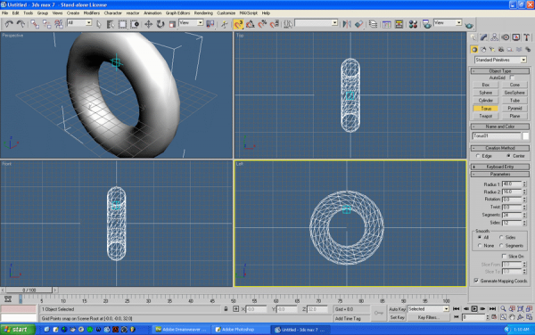
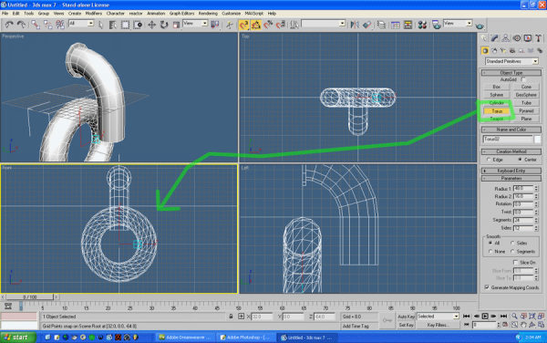
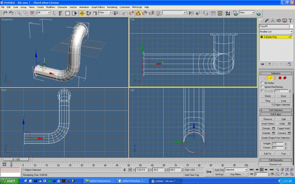
So what primitive is a pipe? A cylinder, what primitive is the curved part of the pipe? A torus, or donut. In this part, we'll bring these parts together to make one model of some nice looking pipes.
Start a new scene (File > New...) and click New All.
Start with the Torus.
Turn the grid snap on if it isn't still on from earlier, and click the center of your world on the Left View. Drag it up to about the first main line, if your grid is still set, it should be 64 units, click again, and pull it down about half as far and click again. Right click it and convert it to editable poly.
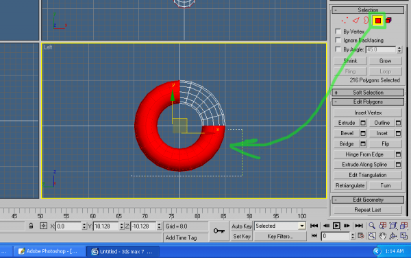
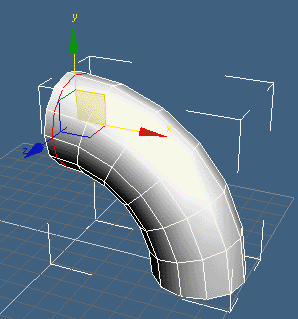
Toggle the Face Select and highlight three quarters of it. You can hold CTRL to select and unselect multiple faces. Now we have a small corner of it perfect for what we need it for. Time to make parts that little hub part that you see attached to the wall. For this, we will use the Slice Plane Tool.
This tool allows up to place a plane that will cut our model into two parts.
NOTICE: Both the Slice Plane and Quick Slice tools alike cut through your enitre model. If you want to cut a certain part without messing up the rest of your model, select the faces you want to be effected then proceed.
To help with this part, you can turn on the wireframe overlay on the perspective view selecting it and pressing F4. Regular wireframe mode is F3.
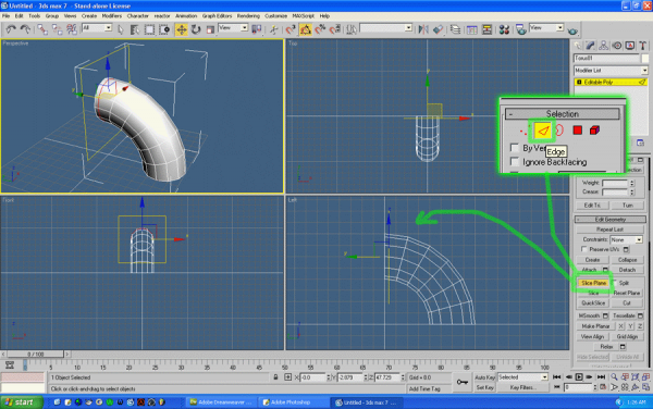
Select Edges and choose the Slice Plane tool. Move the plane as you would regular geometry. If its some weird angle, click reset plane. If its at a different rotation, turn on the rotation snap and rotate it as you see fit.
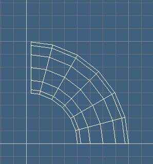
Move near the end of the torus, just and few unit from the center of our world and click the Slice but beneath the Slice Plane tool's button.
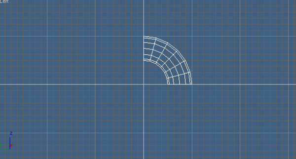
When you turn the tool off, you'll see the result. A nice even new line to work from on your pipe model. Select the faces and delete them. We don't need the ones past the line we just made. Just like the Crate, we'll now pull some geometry out from that, and then back towards the center line which is simulating a wall.
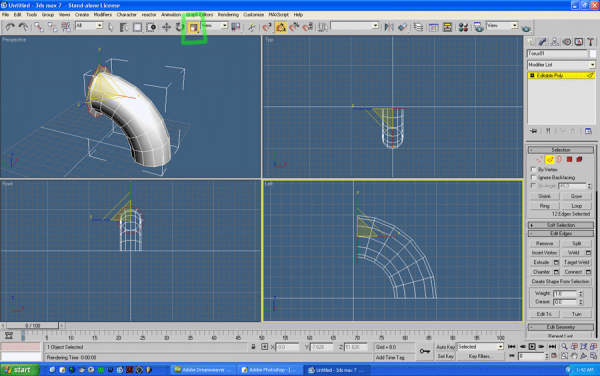
Select the edge you're working on.
(I know, when modelling, you use all of the selections types of Vertex, Edge, Face, Border, and Element. Get used to it and what each one does.)
If we use Extrude like we did before, we'll get an ugly result. The geometry pulled from it will not line up with the rest of it. So we're going to Clone Scale, like Close Dragging only with Scaling. This is an incredibly handy trick many overlook.
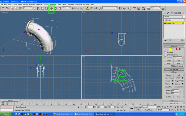
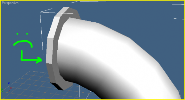
In scale mode, Hold SHIFT and click the large inner triangle of the scale gizmo on your model. It will pull geometry evenly outward on all views. If you selected the outter part of the triangle, it will scale specifically to the viewport you're doing it from. Then there are the handles which can scale in those particular directions. You'll use them all eventually. Now we have a top part to that hub. Switch to the Move tool, hold SHIFT and click and move the red arrow towards the center. The red arrow will keep the movement straight along the axis. It takes the guess work out of it. See that your new faces aren't smooth and round looking? You can fix that with Smoothing Groups. If you know how they work, awsome. If not, here's how.
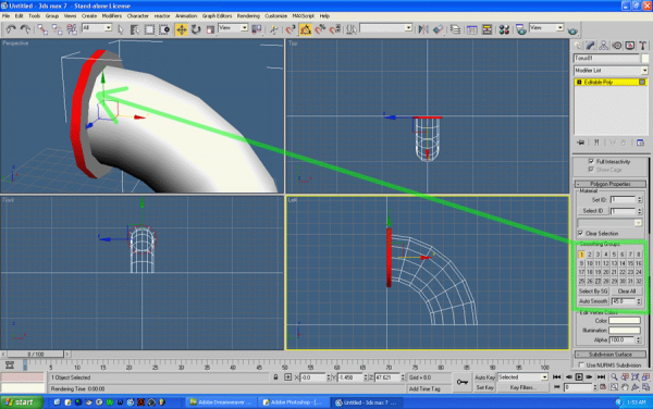
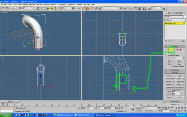
Select those faces and scroll down until you see the smoothing groups, it will be 32 small numbered buttons. When you see it, click the first box and it will smooth your faces together as group 1. If you ever select more than 1 smoothing group, they bridge together just as well. Now is a good time to experiment with what they do. If you map for Source, they introduced the same system of smoothing groups into Hammer. Lets continue our pipe a little. Grab the other end's edges and Clone Drag them down on the front or left view using the appropriate axis arrow. The new faces will not be smooth, so smooth them out.
Next we need another torus like our first one to make the pipe curve. Only this time, make it on the Front view port so we can curve out pipe sideways.
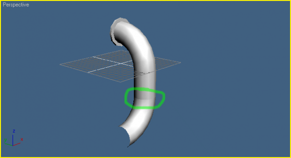
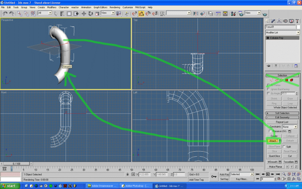
Convert it to editable poly and delete the other 3 unnecessary corners from it. When you line the corner parts up, they make a nasty seam. That is because we have two seperate objects we need to make into one.
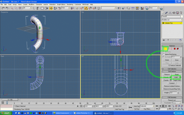
Select the top half and choose the Attach tool and click the bottom half of your pipe. You should have none of the selections enabled for this. It will make both parts into one piece, but we still have a seam. We are going to Weld it together. What better irony then to weld pipes hmmm?
Select Vertexes and click the weld button. It will merge all of the vertexes we selected. If you click the option box to the right of it, you can adjust a threshhold. Its default is 0.1 units by default, meaning any 2 vertexes within 0.1 units of eachother will combine into one and combine geometry.
Lets finish up and extend our pipe from the new corner using Clone Drag and Clone Scale. Also apply Smoothing groups.
If you press 7 on the perspective view, it will show a face count. This times two is roughly the poly count. You should always model with polycount in mind however.
Now... how the hell are we going to texture this? We aren't. We're done. We can't texture this complex bit of geometry without a slightly more advanced tutorial, but save this model for another time though, it will be used in a later tutorial unless you want to make a new pipe. Congratulations! That's the bottom line basics. There are plenty of manipulation tools available. Feel free to explore an see what you can make. As far as texturing goes, you can always select the faces you want textured and drop texture onto only those faces, then UVW Map only those faces. There is a lot of power in that if you be creative, but if you map with Hammer, take it from that point of view and make something you can use and share. Remember these basics.
- Categories
- Tutorials
- Beginner Tutorials
- Goldsource Tutorials
- Modelling
- Article Credits
-
 Rimrook
–
Original author
24 Comments
You must log in to post a comment. You can login or register a new account.



Great job, this should've been done sooner. :>
But seriously, GMax doesn't work with this tutorial. Works and looks too different. Inset for example, is not available, only Extrude and Bevel. Fail.
What are you going to do about this?
If you export the model without a bone then it will pick the origin of the grid(black lines).
I know there are minor differences between the two. Gmax was built from Max4, which Half-Life was also built on Max4, it may actually work better. If all else fails, there is Milkshape.
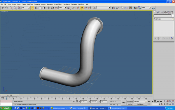
I've finished the shipment of win and the pipe model.
W00t!
http://bildupload.sro.at/a/images/ns_urhm0000.JPG
you gonna make a sequel, with all the complexities in it, like animation?
This.
Oh well..