Tutorial: Animating Models Last edited 2 years ago2022-10-10 22:52:13 UTC
Create a Model to Use as a prop_dynamic
✔️ Download example fileThis tutorial will take you step-by-step through creating the geometry for an animated model in XSI, texturing the model, exporting the required smd files from XSI and compiling the model for use as a prop_dynamic in Hammer (Source). It's written in such a way that you'll learn a few more XSI skills and tools.
This tutorial assumes you know how to use XSI basics, to the level introduced in my tutorial for A Half-Life 2 Simple Model. This tutorial will introduce you to additional basic tools for manipulating your geometry and animating your model in XSI.
In this tutorial you'll create a simple object geometry from several cylinders. You'll texture the geometry and animate it to simulate an object with a simple pump-like action. You'll export three smd files for your animated model, compile them using Source compiling tools and view the results in the Half-Life Model Viewer.
Getting an Image to Texture the "Pump"
Download the zip file using the link at the bottom of this tutorial. Unzip the texture (metal.tga) into a folder somewhere. It's simple texture used for demonstration purposes. Texture for the model
Abbreviations Used In This Tutorial
- LMB: click with the Left Mouse Button
- MMB: click with the Middle Mouse Button
- RMB: click with the Right Mouse Button
Creating the Geometry
Open XSI and Get->Primitive->Polygon Mesh->Cylinder. Change the Radius to 2 and the Height to 8.First, we'll create a "machine part" that you'll duplicate a couple times to use creating the geometry. You'll do this by extruding parts of the cylinder to create some joints simulating a ball-and-socket.
LMB the face select tool above the Camera view.
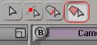 Face select button
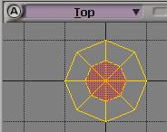 Top polygons selected
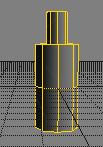 Top of the part is extruded
Select the face select tool and, on the bottom of the cylinder, LMB the two outer faces on the left and the two outer faces on the right.
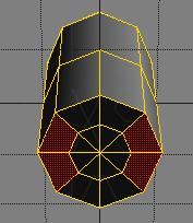 Selected polygons on the bottom of the part
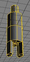 Top and bottom extruded
Apply the Texture to the Machine Part
LMB the Object Select tool button and, in the main menu, LMB Render->Get Texture->Image. Answer yes when asked to save local materials.Doing the same as in the Simple Model tutorial, LMB the Edit button by the noIcon image, scroll down and LMB the "..." button, navigate to your copy of the gray_cyl.tga file and select it. LMB the left arrow at the top of the image properties dialog, scroll down and LMB the New button in the Texture Projection part of the dialog. Select Cylindrical and close the dialog.
Select Textured Decal in the camera view and see that your cylinder is now textured. For the purposes of this tutorial, the texturing is adequate. If you want to enhance the texturing (only the sides of the cylinder are really mapped correctly), open up the Texture Editor (alt-7) and make adjustments to suit.
Building the Model Geometry
To make a more interesting model, we'll need two more parts identical to the one you just constructed. Before you duplicate it, ensure that the texture mapping information for the object gets copied by going to the main menu and LMB Edit->Duplicate/Instantiate Options. In the Duplicated Items portion of the dialog, under Texture Supports, select Always duplicate and close the dialog.Make sure the object is selected and press ctrl-D to create a duplicate. The duplicate overlays the original part and is now selected. Using the translate tool, move the duplicate out of the way along the z axis a ways. Create the third part you'll need by pressing ctrl-D again. Check in the camera view that you have three identical parts lined up along the z axis.
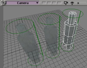 Duplicated parts
Select the original part, the one at the origin of the grid. In the Transform panel, LMB Global and LMB the r button and the x button to select the rotate tool about the x axis only. In one of the views (Right view is shown below), LMB drag the red rotator and rotate the object 90 degrees. If you don't get it exact, edit the rotation number in the Transform panel.
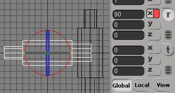 Rotate the first part
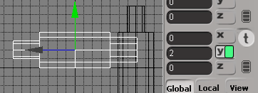 Translate the first part
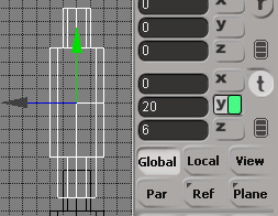
Select one of the other two parts and translate it to a y value of 8 and a z value of 6.
 Translate the second part
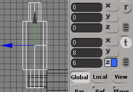
Select the third part of your model and translate it to a z value of 6 and a y value of 20. Freeze all transforms for the last part of the model.
 Translate the third part
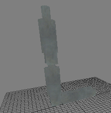 The textured geometry
Adding Bones
It may take a couple of tries to get used to adding bones to your model. Save your XSI project at this point. If things get really messed up when you're adding bones, you can reload and start from this point.Before you animate your model, you have to add bones to it. The bones will be used to move the model into the desired positions for the animation.
Adjust the Right view so you can see the first part in entirety. Deselect all objects.
In the Model toolbar, LMB Create->Skeleton->2D Chain. Holding CTRL down for snap-on-grid, LMB once at the position of the white cross shown below to locate the root of the chain.
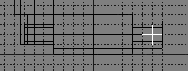 Position the first root
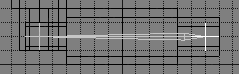 The first bone
Adjust the Right view so you can see the entire second part. In the Model toolbar, LMB Create->Skeleton->Add bone to chain. In this step, you'll LMB drag the bone. Unlike creating a chain, adding a bone is a single LMB drag operation. The root of the chain has already been created (the single click you did before you added the first bone). So, don't click and release until the bone is created.
With CTRL pressed, LMB drag from the effector location upward to the intersection of the second part of your model with the third part, as shown. Note that the effector for this chain moved with the bone you added. Deselect all objects.
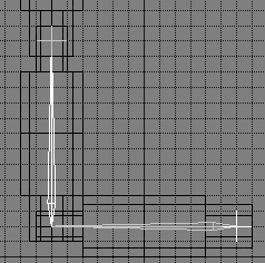 The first bone chain
Adjust the Right view so you can see all of the third part of the model. The third part of the model isn't going to flex with the first two parts so we're going to add a new 2D chain, just for the third part.
Add a new 2D chain (not just a bone) with the root at the same location as the effector for the first chain and the effector at the top of the third part, as shown on the left below. The bones of your model should now be arranged as shown on the right below (although not highlighted).
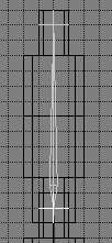 The second bone chain
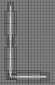 Both bone chains
If you didn't get it right the first time, that's not at all unusual. Reload your project and try it again, following the steps above.
Animating Your Model
LMB at the top of the Model toolbar and select Animate, or just press 2 to select the Animate toolbar.At the bottom left in the Context section of XSI (below the Animate toolbar), LMB drag the down arrow beside Modeling and select the Animation construction mode.
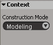 Mode selection
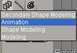 Selecting Animation mode
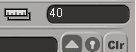 Setting the number of frames
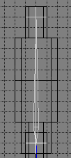
Zoom in the Right view until you can easily see the first part of your model and the first bone. Select the first part of your model, the horizontal cylinder (LMB drag in one of the views across any part of the object). In the Animate toolbar, LMB Deform->Envelope->Set Envelope.
LMB drag the first (horizontal) bone and RMB to set the envelope. The first part should be selected with blue vertices.
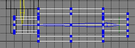 First part enveloped
In a similar way, select the second part of your model and set the envelope to the second bone. Do the same with the third part of the model and the third bone.
Close the dialog box (nothing to change there) that pops up when you RMB to set the envelopes. If you select all three cylinders (hold down shift and LMB drag each one), you'll see that all three objects have had envelopes set to bones (hopefully the correct object with the correct bone).
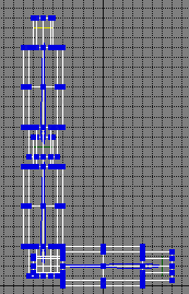 All parts enveloped
If you want, save your project again, perhaps with another name, to save your progress to this point.
In the animation controls at the bottom of the screen, LMB the rewind button and check that the red indicator in the frame bar is at the far left and frame 1 is indicated in the current frame box.
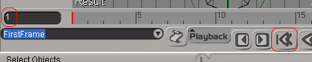 Positioned at the first frame
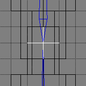 Effector for the first chain selected
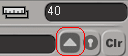 Checking selection
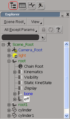 The scene explorer
With the effector for the first bone selected, in the first frame, select the translate tool and LMB the y axis button. Notice in the animation bar at the bottom that the key button has changed and the box to the right now indicates you're going to set a local position.
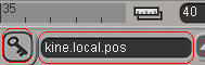 Ready to set a key frame
The current position for the first chain is also the position where you want it for the last frame (returning to its rest position). In the frame bar above the key button, LMB between the last tick and the far right of the bar to select the 40th frame. The red frame marker will move to the last position and the key button will turn green to indicate that the position for the selected object (in this case, the effector for the first chain) has not been set for this frame.
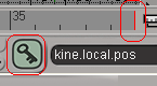 Ready to set key in frame 40
In the frame bar, LMB over the number 20 to set the selected frame to the middle of the animation. The key button turns green.
In the Right view, LMB drag the effector to a y value of 20 and LMB the key button to set the position for the first chain in frame 20. The button turns red.
Deselect the translate tool and all objects.
LMB the loop button in the animation controls (the button with the "circular" arrow) and LMB the play forward button (the button with the right pointing arrow) and watch your animated model move smoothly up-and-down.
In the last several steps, you've set the position of the first chain of bones to its rest position in frame 1 and frame 40. When you set the position of the chain in frame 20, XSI calculated for you all the intermediate steps for the frames between frame 1 and frame 20, and between frame 20 and frame 40. Because you set the envelopes, the geometry part of your model (the first two cylinders) followed the moving bones.
LMB the play forward button to stop the animation. LMB the rewind button to set the animation to the first frame.
Because you selected only the effector for the first chain, the movement of the effector "dragged" the bones with it. It simulates the top of the second bone (at the effector) being "pulled" up, pulling the bone and the joint between the first and second bones. The joint moving up "causes" the first bone to move up. Because the root of the chain is fixed in position, the first bone is constrained to rotate about the root. An appropriate motion for two fixed-length bones flexing is simulated.
Now you'll set the positions for the third part of the model. This time, however, you'll set the positions for a straight up-and-down motion, rather than a motion rotating about the root of the second chain.
To do this, the effector, the bone and the root must all move in unison, so they all must be selected to move.
RMB drag the effector for the second chain. By using RMB, rather than LMB, the entire chain is selected, including the root.
 Second chain selected
In any case, the second chain is selected. Make sure you're in frame 1 to start. Select the translate tool and the y axis, and, without moving the chain, set the keys for the chain in frames 1 and 40.
LMB frame 20. Conveniently, the first chain moves to its frame 20 position. With CTRL down, LMB drag the selected chain up (along the y direction) until the root of the selected chain is in the same position as the effector for the first chain. Set the key position and deselect the translate tool and all objects.
 Second chain positioned for frame 20
Save your scene and get on to exporting the files you'll need to compile a model suitable for use as a prop_dynamic in an HL2 map.
Exporting smd files
If haven't done so, go into Windows Explorer and create a folder [your_steam_logon]/sourcesdk_content/hl2/modelsrc/models/pump in which to store your smd files.
Back in XSI, in the main menu, LMB ValveSource->Export smd...
In the SMDExportProperty dialog, underOptions, select Model (.SMD) as the File Type. LMB the "..." button beside the filename box above and navigate to the folder where you want to store your smd files. In the filename box enter "pump_ref" and LMB the OK button to return to the SMDExportProperty dialog. LMB OK to save the reference model file.
LMB ValveSource->Export smd... again and select Physbox (.SMD) as the file type. LMB "...", navigate to your smd folder and enter "pump_phys" as the filename. LMB OK and LMB OK again to export the bounding box information.
Lastly, export a Skeletal Animation (.SMD) type file with the name "pump_idle."
Close out XSI.
Compiling the model
In Windows Explorer, navigate to your smd folder and check that you have ref, phys and idle smd files, about 100K apiece for the first two and about 8K for the idle file.Open up Notepad and enter the following text, including the quotation marks.
$modelname pump/pump.mdl
$cdmaterials models/pump
$surfaceprop "metal"
$scale 3.0
$body studio "pump_ref.smd"
$sequence idle "pump_ref" loop fps 1
$sequence pump "pump_idle" loop fps 15
$collisionmodel "pump_phys.smd" {
$Mass 100
}The $modelname line will tell the compiler to create a new folder under the HL2 folder for models named "pump" and put the compiled model into a file named pump.mdl in that folder.
The $cdmaterials line tells the compiler that the texture for the model will be found in the HL2 materials folder under the folder models/pump.
I set the scale to 3 for this model to give it what seems to be an appropriate size. Change it as you like to create a model of the size you want.
By setting the idle sequence to the reference file, the model will be normally at rest in your map. By triggering the models animation to pump, the pump will animate. You can simulate turning the pump on-and-off this way. If you use the pump_idle file as the idle sequence, it will pump all the time and you won't be able to turn it off.
Drag-and-drop this .qc file onto studiomdl.exe in the sourcesdk/bin directory.
If you haven't created it, create the folder [your_steam_logon]/half-life 2/hl2/materials/models/pump.
Drag-and-drop the gray_cyl.tga file onto vtex.exe in the sourcesdk/bin directory. If needed, move the resulting gray_cyl.vtf file into the HL2 materials/models/pump folder you created.
Open up Notepad and enter the following text, including the quotation marks.
"VertexLitGeneric"
{
"$basetexture" "models/pump/gray_cyl"
"$surfaceprop" "metal"
}Open up ModelViewer and navigate to your models/pump folder. Double-click on pump.mdl and view your new animated model.
Using your model in an HL2 map
Open up the Hammer editor and put a prop_dynamic entity in it. Open up the properties for the prop_dynamic and choose your model by browsing the World Model property. Set the Default Animation to "idle" (without the quotation marks). Set the name for the entity to "pump."Add two buttons. In the first one, set the output to OnPressed, entity "pump," SetAnimation, "pump." Set the output for the other button to OnPressed, entity "pump," SetAnimation, "idle."
Compile the map and run it. One button will start the pump animation. The other button will stop it.
Have fun with HL2 modeling using XSI!
- Categories
- Tutorials
- Intermediate Tutorials
- Source Tutorials
- Article Credits
-
 BJ
–
Original author
BJ
–
Original author
Comments
You must log in to post a comment. You can login or register a new account.