RUST: The BSP Process and Visibility Last edited 5 years ago2019-11-09 10:48:58 UTC
You are viewing an older revision of this wiki page. The current revision may be more detailed and up-to-date.
Click here to see the current revision of this page.
The BSP Process and Visibility
Introduction
This tutorial is written for Quake II and to some extent Quake 3 Arena. However, all Quake engine games work on a similar principle (though not all have hint brushes or detail brushes).The Map
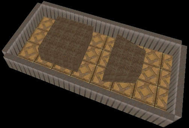
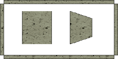
The examples in this tutorial are going to use the following map, which consists of 4 walls, and 2 objects in the middle:We will use the following overhead view for this tutorial:This map is a 2 dimensional map. Lines in this map will correspond to polygons in the 3 dimensional map. The polygons in this 2 dimensional map will correspond to brushes in the 3 dimensional map.The BSP Process
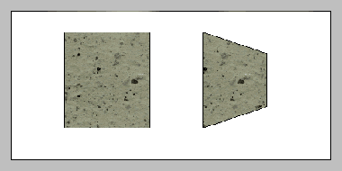
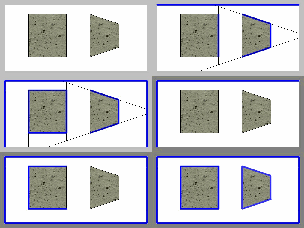
There are 12 extraneous polygons on the outside walls of this map, so let's simplify matters a bit by eliminating them (which will happen anyway during the BSP process if there are no leaks):The gray area around the edge will represent the part of the world we do not care about since it will be outside the play area. There will be some additional bsp splits by the 12 eliminated surfaces out here but nothing that will affect the interior of the map. White is the empty area a player can move around in. The stone is solid.During the BSP process qbsp3 takes each polygon one by one and inserts them into the bsp tree. The term tree describes the data structure the bsp nodes are stored in (if the data structure is drawn graphically on a piece of paper, it looks something like a tree or bush). As each polygon is inserted, it will split space up into smaller and smaller regions, but it will only split up the regions it is inserted into. The process is shown graphically below (if this image is not animating, reload the page and don't stop the loading of the page, or open image up in a separate browser window):As you can see, the order the polygons are inserted have an effect on how the map is broken up. Adding, deleting, or changing a single brush can cause qbsp3 to go into an entirely different direction and cause significant performance changes (either better or worse).
In reality, qbsp3 uses certain rules to select which order to insert polygons. First it assigns a really high priority to axial polygons. These are polygons whose X values are all the same, Y values are all the same, or Z values are all the same (in the editor, in 2 of the 3 possible 2d views, the polygon will show as a simple line). After that, it will look for polygons that will split up the remaining uninserted polygons the least. The bsp animation with the darker gray border is the one much more in line with what qbsp3 will actually do. However, for this tutorial, I am going to use the one with the lighter gray border for illustrative purposes.
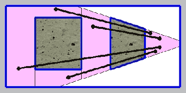
Both the thick blue and thin black lines lie on what are known as bsp split planes. They break the map up into small (or sometimes, not so small) regions. Each of these regions is a bsp node. You will never find a world polygon in the middle of a bsp node. They all lie on a bsp node edge/side. Moving objects, etc. are not part of the bsp tree and are handled separately.
The thick blue lines are your solid polygons. You can't move through them. They are almost always visible. If it is not visible for whatever reason, you will probably wind up with what is known as the Hall Of Mirrors (HOM) effect or see other, further parts of your level through it.
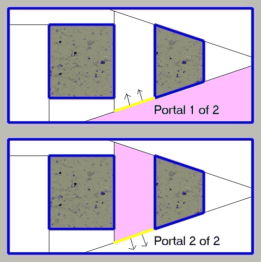
The thin black lines are what become your portals. Portals separate bsp nodes where there is no solid polygon. They are not visible, but polygons generated with a mist-ed brush, or other non solid brush can overlap them. They do not block movement. There are actually 2 between any 2 bsp nodes (where there is no solid polygon). Each of those 2 portals is attached to its respective bsp node. See image below (if this image is not animating, reload the page and don't stop the loading of the page, or open image up in a separate browser window):The arrows indicate which way the portal faces. The shaded node is the node the portal is attached to.
When a polygon is inserted that is inside 2 or more bsp nodes, it gets split into several pieces such that each piece is in a single node. However, qbsp3 will later to try to merge faces with identical properties together if possible (so you may have a single polygon attached to multiple bsp nodes), so you often wont see evidence of this effect if you turn on gl_showtris (see discussion of gl_showtris below).
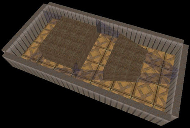
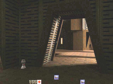
The following is a 3d representation of this map in Quake II:The thin semi-transparent windows represent the portals which you can't normally see.
Visibility Nodes
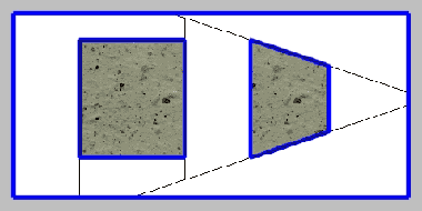
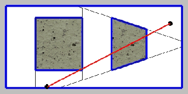
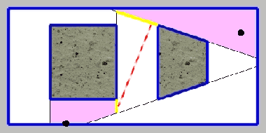
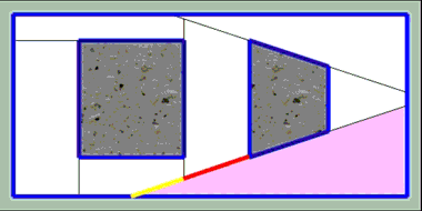
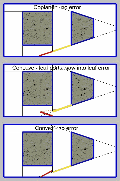
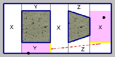
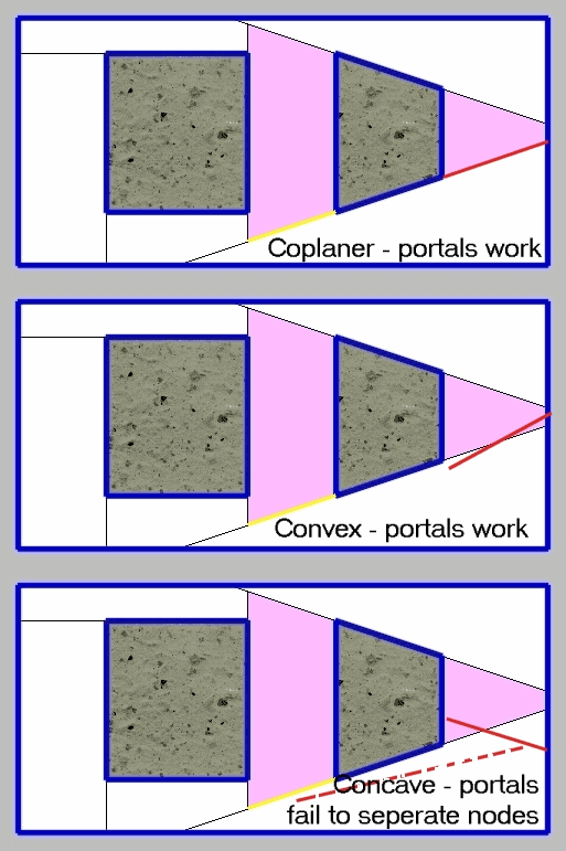
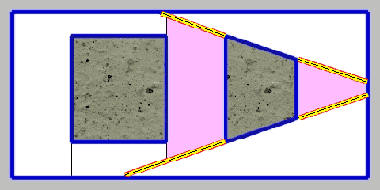
Lets take the following possible final bsp arrangement (from one of the example bsp-ings above):As mentioned above, each of the white areas is a bsp node. These bsp nodes are also used for visibility determination. Qvis3 goes through and determines which nodes are visible from which nodes. Lets take the following 2 points, one being an observer, another being a point on a wall that is being looked at:As you can see by the red line, the two points are not visible too each other. However, with this bsp, qvis3 (and thus Quake II) will think they are. Why is this? Because the nodes they are in are visible to each other. Qvis3, when checking for visibility, checks each portal against each other portal. If it finds 2 portals that can see each other, then the 2 bsp nodes they are part of can see each other. In the following image, the portals currently being looked at are marked in yellow.Since they can see each other (1 of the infinite number of possible lines of sight is marked in a dashed red line), the bsp nodes the black dots are in can see each other. This means that as far as qvis3 and Quake II are concerned, the observer can see the point on the wall.This, by the way, is where the infamous "Leaf portals saw into leaf" warning comes from. When this happens, it means it tried comparing 2 leaf portals that belongs to the same visibility node. There was a nasty bug in the original qbsp3 (yes, qbsp3. It wrote out a bad bsp that qvis3 had problems with) that resulted in seeing this error often. Seeing it often meant that there were serious problems with the map. However, a number of rewritten qbsp3's fixed this problem. Even with fixed qbsp3's, you may still see the warning. Take a look at the following:The red and yellow portals were originally 1 portal that got split into 2. Normally, qvis3 takes steps to prevent unnecessary portals from being checked against each other, but this can fail. Both the shown portals should lie on the same plane, but due to limitations of floating point numbers as they are represented in computers, they may be slightly bent with respect towards each other (by a real small amount you could never hope to see with the naked eye). If this happens, and they bent in a concave fashion, you will get this error. The following picture shows what this looks like (if this image is not animating, reload the page and don't stop the loading of the page, or open image up in a separate browser window):The angles are highly exaggerated. The dashed line shows how the node saw itself. In this situation, the warning is harmless.
There are several other similar situations where you might see this warning, all the result of a computer's finite precision floating point math. If you have a fixed qbsp3, do not worry about this warning.
If the portal in question is axial, this should not happen.
Checking Visibility
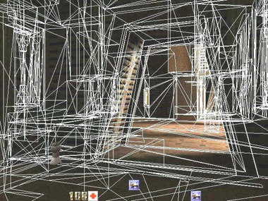
So you have your map up and running and want to see how visibility worked out where you have speed problems. The primary way of doing this is using one of the OpenGL rendering modes, then setting gl_showtris 1. Take the following view from base64 (deathmatch compilation of base1, base2, and base3 from the single player game):And now with gl_showtris 1:This shows us that Quake II believes that a lot of polygons are visible when they really are not. It is showing all the polygons in all currently visible nodes. In case you are wondering, I removed the player weapon by typing "hand 2" at the console.The triangles are not part of the bsp. When polygons are rendered, they get broken up into triangles in the engine.
3Dfx Cards
The 3dfx minidriver does not support gl_showtris. You can use the default OpenGL drivers, but if you are using the software OpenGL (Microsoft's or SGI's), it will be really slow, and possibly somewhat unstable. You can also load the MesaGL driver for 3dfx cards. Once you have the drivers, put it in your Quake II directory (DO NOT put it into your system/system32 directory). Make sure it is named opengl32.dll if it isn't already. Now when you use default opengl drivers, it will use the Mesa drivers (which the above screenshot was taken with).Still Not Seeing Triangles?
If you do not see triangles, you may need to issue the following commands at the console:gl_ext_multitexture 0
vid_restartgl_ext_multitexture 1
vid_restartHint Brushes
In the example bsp, there are only 4 pairs of bsp nodes that are not visible to each other (shown marked below):There are 21 possible pairs of bsp nodes, only 4 of which are hidden from each other. This is not good. It will result in problems similar to above in the base64 map. The base64 scene above is actually not too bad but you can get more extreme examples where you may be drawing the same part of the screen 3, 4, 5, or more times. In the original Quake, mappers were forces to go through various games to keep visibility reasonable. Fortunately, Quake II gives us a tool with which we can control bsp-splits: the hint texture. What does the hint texture do? The hint texture is a texture that forces a bsp split even though the hint texture is not visible. Another feature of the hint texture is that qbsp3 will not chose a polygon insertion order that will result in a non-hint polygon splitting a hint polygon.The hint texture is typically used in conjunction with the skip texture. The skip texture polygons are not inserted into the bsp-tree and thus, not used by Quake II. The idea is to take a brush, apply the skip texture, then apply to a single side of the brush the hint texture. This will result in a single hint polygon inserted where the brush is, which is generally all that is necessary. However, you can use an entire hint brush, but this will make the bsp-splits a bit more complicated.
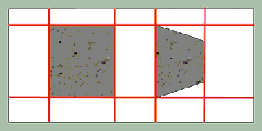
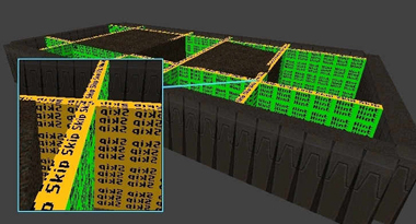
When you lay out your hint planes, you have to place them such that two areas you intend to keep hidden from each other don't have the hint planes facing each other. For the example map, we will try a grid as follows:In an editor (this particular shot came from Qeradiant), it will look something like this (except for the inset):The inset shows the area at the base of the line from another angle.
These brushes all have 5 skip faces, and 1 hint face. The skip faces are completely ignored, only the hint faces are processed. We could reduce the number of hint/skip brushes down to as few as 3 by using more than one hint face per brush but for this example, we will use 1 hint face per brush (for one thing, by keeping the brushes thin, they don't clutter up the view in the editor as much).
The 2 points we used above are still going to be visible to each other as the new nodes they will be in will still be visible to each other:However, there are more areas hidden from each other. None of the areas marked with the same letter will be visible to each other. There are additional areas not visible to each other (for example, the nodes in each set of opposite corners) which would have made the diagram too complex and confusing if completely listed. Visibility will never be perfect. At any given point in your level, there will be parts of your level that are not visible but will get drawn anyway (with a few exceptions like facing an outside wall with nothing behind it).
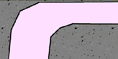
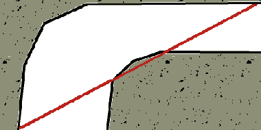
It will take some trial and error to get a feel for what works well. Deciding where to place hint planes can be something of an art form. One good use for hint brushes is in hallway bends as follows:You can keep people from seeing too far around the bend by laying a hint brush across the corner like this:This way you make sure you can only see down both hallways at once if you are in the corner. In addition to placing hint brushes where you want portals, you can place them in the void or in geometry to separate parts of the level from each other. For example, if your map consists of 2 separate parts connected only by teleporters, putting a huge hint brush (such that you cannot connect any 2 points, one from each part, without going through it) between the 2 parts will keep brushes in either part (except for other hint brushes) from causing bsp splits, etc., in the other.
Detail Brushes
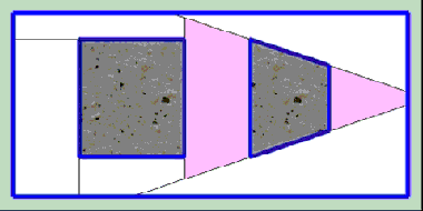
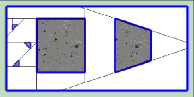
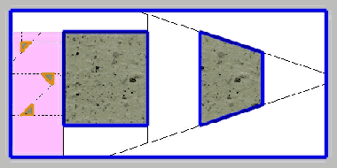
Lets take our previous map, and add a few small brushes. The final bsp might look something like this:As you can see, the number of bsp nodes has increased from 7 to 13. The number of nodes to run bsp calculations has almost doubled and will cause the size of the visibility information to nearly quadruple. However, the new brushes do practically nothing to block visibility, making the visibility information needlessly complex. In the original Quake, this was a fact of life you pretty much had to live with. With Quake II, like the hint texture above, we get a tool to help us out: the detail brush. Unlike the hint texture, which is applied to individual brush faces, detail is a property that applies to the entire brush.What happens with detail brushes, is that the polygons making it up are inserted into the bsp tree last. Additionally, when detail brush polygons are inserted, they do not create ortals, and the bsp nodes they cut up are treated as one single visibility node. Lets make the 3 triangular brushes detail brushes. Then we will end up with something like:The dashed lines are bsp splits, but do not contain portals. Qvis3 treats the entire shaded area as a single node for visibility calculations. This greatly simplifies the qvis3 process and makes it a lot faster. When deciding if a brush should be a detail brush or not, you should pick those that look like that could be seen around easily. Good candidates for this are things like beams, light fixtures, computer terminals, pretty much anything small that doesn't do a good job of blocking visibility.
This can be tricky and will some take some trial and error to get a good feel for. You will want to use gl_showtris mention above as an aid to this process.
Detail Hint Brushes
Detail hint brushes are not part of id's original compiling utilities. If you are using those, you will not be able to use this feature. They were primarily implemented as an aid to terrain generators to keep detail brush based rolling terrain from cutting itself up. Gensurf is capable of using detail hint brushes (it also comes with its own version of qbsp3 that also implements detail hint brushes).Credits
Tutorial written by Geoffrey DeWanMany thanks to those who have helped proofread and give suggestions for this tutorial:
- SmallPileofGibs
- bushboy (for the optimized images)
- some guy I know
- EutecTic
- Johnny Law
- XO (for pdf version)
- Categories
- Archived Articles
- RUST Archive
- Tutorials
- Mapping
Comments
You must log in to post a comment. You can login or register a new account.

