Tutorial: Finding center of rotation from initial and final positions Last edited 5 months ago2024-09-26 14:18:17 UTC
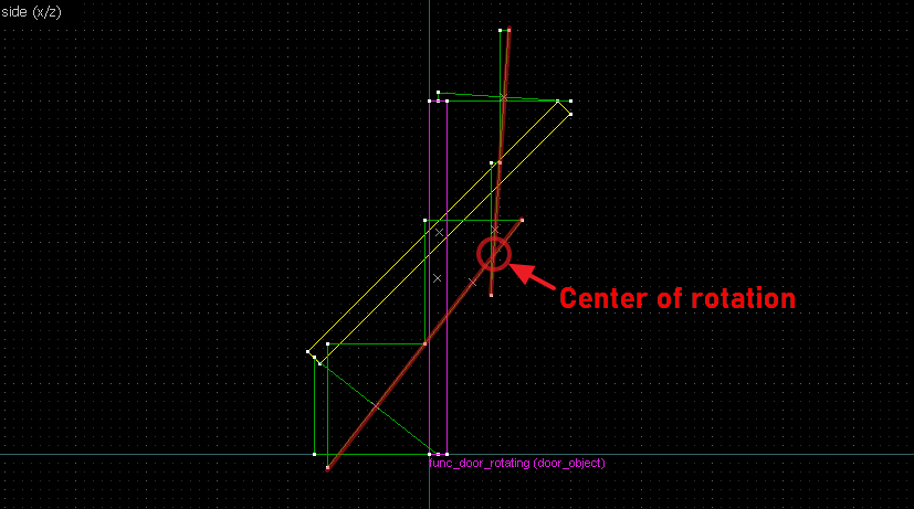
A little lesson in geometrical construction, to find the center of rotation between an object (initial position) and an image (final position). This will help you in building rotating doors that rotate to any final position (or as close to it as J.A.C.K./Hammer allows you).
Throughout this page the terms object (original position) and image (position after rotation) may be used to refer to an entity's initial and final positions, or in case of doors, the closed and open positions.
Principle
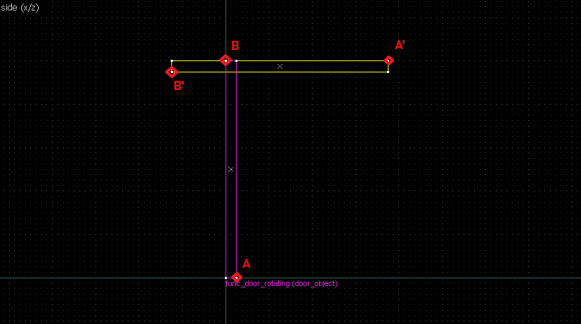
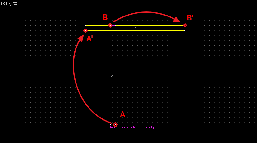
Finding the center of rotation boils down to the following steps:- Identify 2 reference points from an object, and the corresponding points on the image.
- Draw straight lines between the object and image for both points.
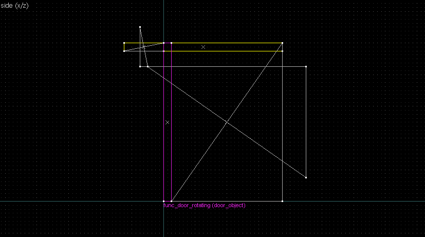
- Draw a perpendicular line for each of the lines at the midpoint (perpendicular bisector).
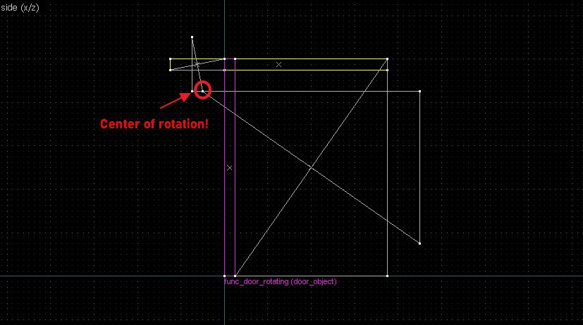
- The intersection of the perpendicular lines is the center of rotation.
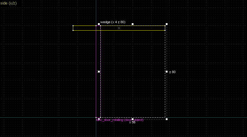
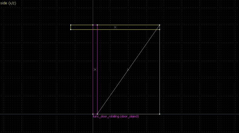
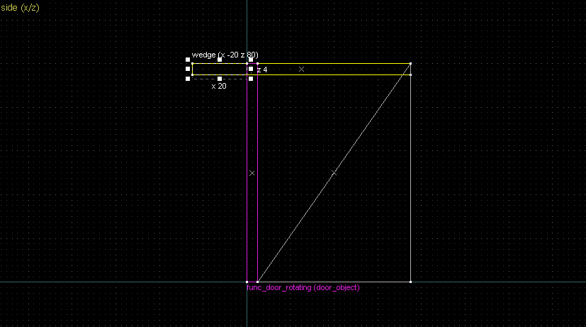
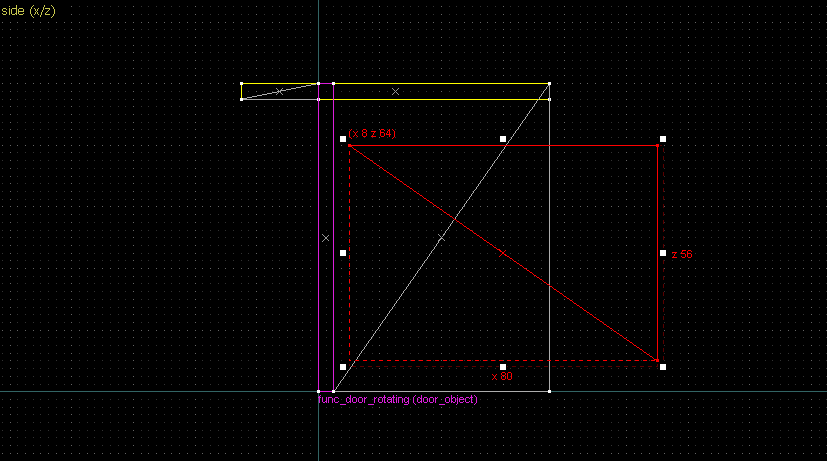
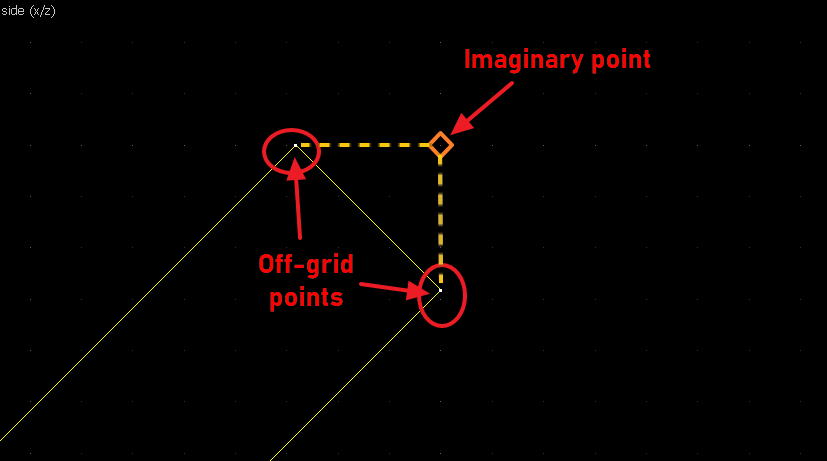
- Drawing a straight line between two points → Wedge primitive.
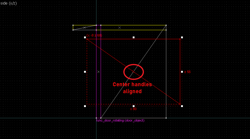
- Drawing a perpendicular bisector → Rotate the wedge 90° and align the center handles.
- Extending a line → Clone the wedge and align the ends.
Tip: Use the  SKIP tool texture for your geometrical construction. This will be removed by compiler with no effect to the rest of level geometry, so it is safe to [accidentally] leave them in.
Examples
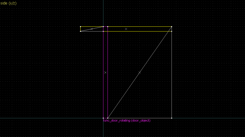
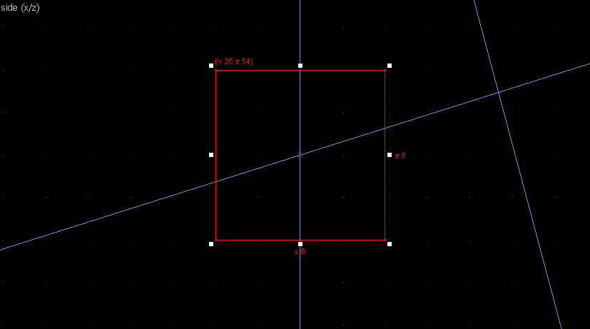
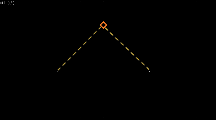
1. 90° rotation
Suppose we want to have following rotation: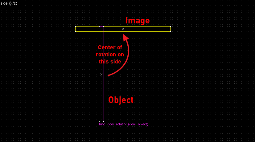
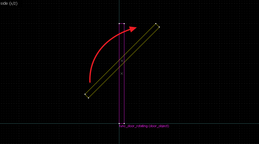
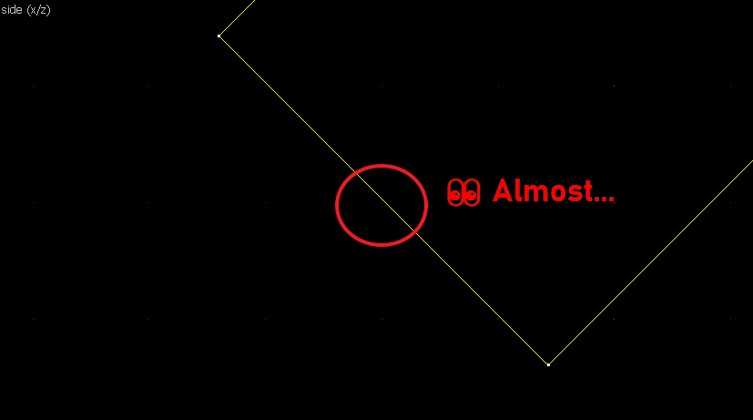
2. 90° rotation (but the other way)
Let's do another 90° rotation, but now it goes the other way: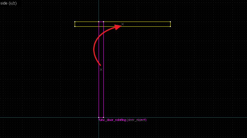
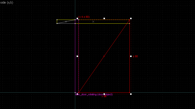
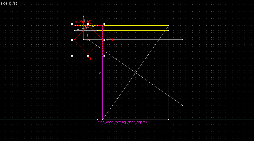
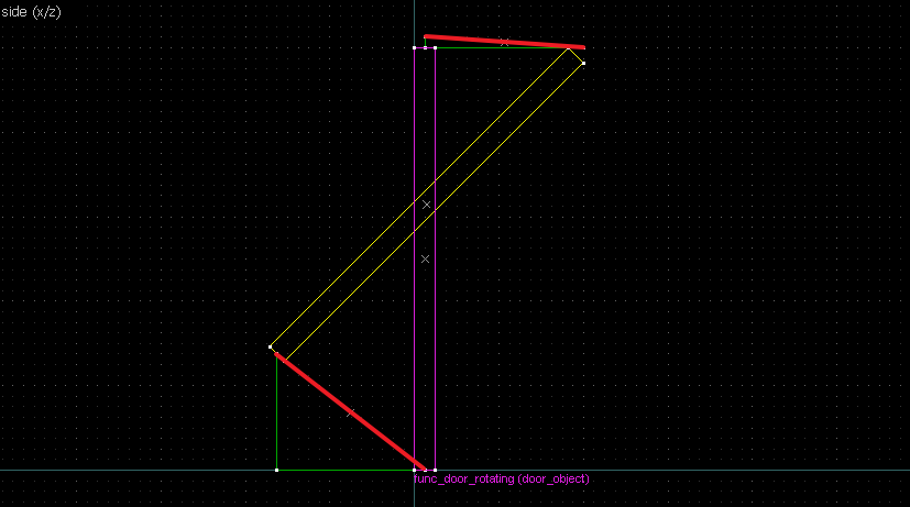
 Relevant edges highlighted red
The intersection of the bisectors are our center of rotation.
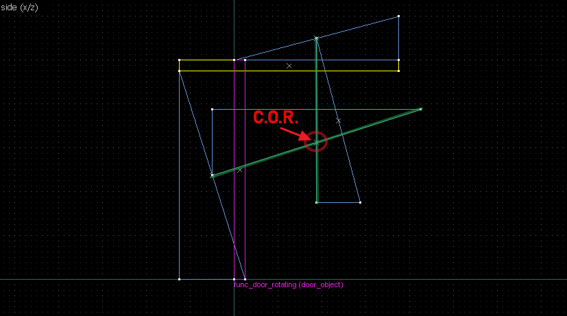
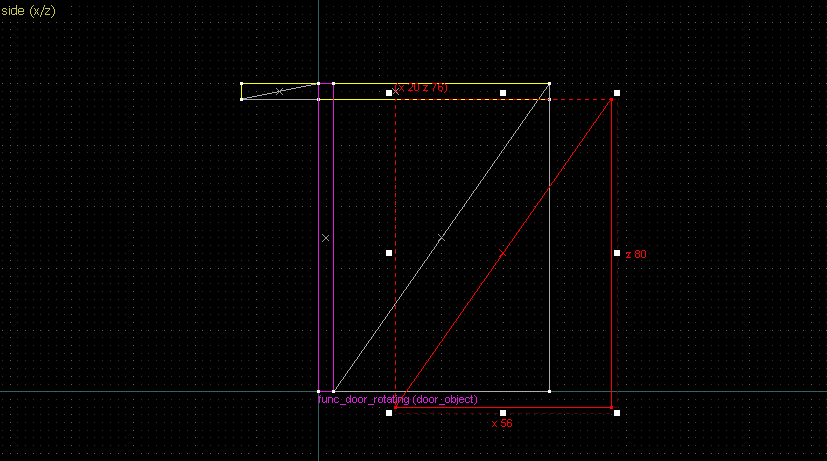
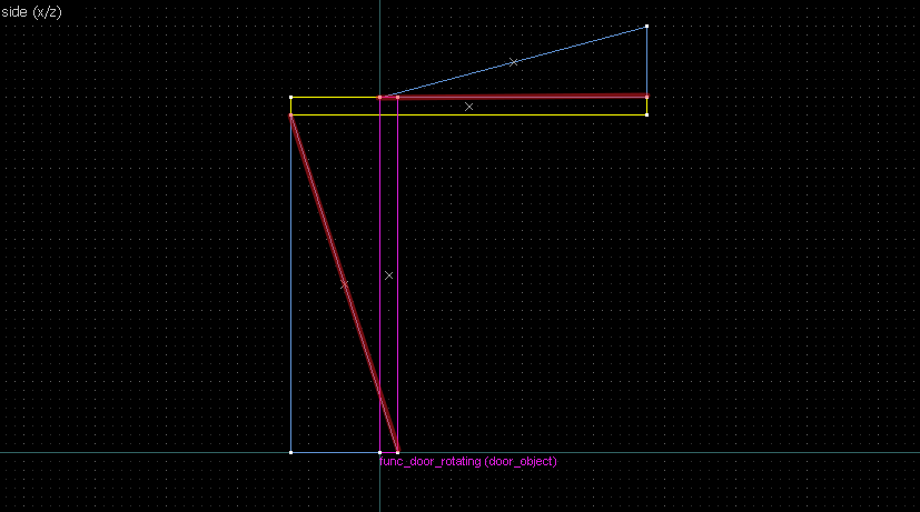
3. 45° rotation
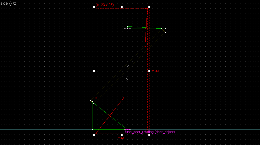
 Bisectors highlighted in red
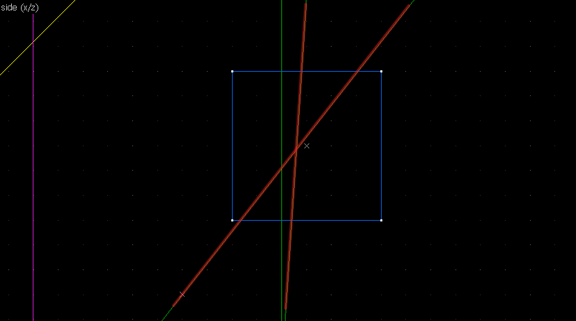
Conclusion
Provided the angle of rotation is known beforehand, you'll now be able to place any kind of rotation where the final position would be where you want it to be (or close enough). Hope this helps realize some epic, crazy setups in your minds!- Categories
- Tutorials
- General Tutorials
- Mapping
- Article Credits
-
 kimilil
–
Original author
kimilil
–
Original author
Comments
You must log in to post a comment. You can login or register a new account.


