Tutorial: First XSI Model Last edited 2 months ago2024-09-20 03:26:48 UTC
Create a model to use as a prop_static
This tutorial assumes that you have XSI EXP v4.2 (from Softimage) installed, including the ValveSource addon. This is a very basic tutorial, walking you step-by-step through:
- basic navigation inside XSI
- creating a simple polygon mesh cube model
- texturing the cube using UV mapping
- exporting a Half-Life Source reference smd file which you can compile into a model using Source SDK tools
For this tutorial, I'll assume you're using the same resolution and layout and see and can access the buttons I mention.
In addition, I'll assume you're using a three-button mouse. Many of the selections you make in XSI will depend on whether you use the left, middle or right mouse button to activate them. If you have a scroll mouse with a scroller as the middle button, pressing the scroller to click as a middle button will work fine.
If you just started up XSI, you should see a vertical buttonbar on the left titled Model, a horizontal row of buttons across the top under the main menu above four windows, and a vertical button bar on the right with Select and Transform sections.
For this tutorial, you won't be using the other features you may see, such as the Animation and playback horizontal toolbar, at the bottom.
Note: If you don't see a ValveSource menu item in the main menu bar just under the Softimage window title bar (probably to the right next to the menu items Window and Help, you don't have the ValveSource addon for XSI EXP v4.2 and you won't be able to export Half-Life compatible smd files. Download the ValveSource addon from Softimage and install it!
Before we get started into the modeling
I'm going to use some abbreviations to make things a little simpler.
- LMB: Click the left mouse button
- MMB: Click the middle mouse button
- RMB: Click the right mouse button
- LMB (or MMB or RMB) drag: Click the button and drag the mouse to the desired position
If you need (or want) to change the layout, go to the menu underneath the Softimage title bar, LMB Application->Layouts and select a layout from the list. The layout Laptop 1280*800 may suit you better and should work well with this tutorial.
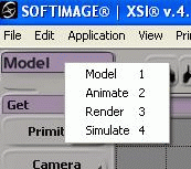
The vertical buttonbar on the left can be changed by LMB on the bar title (Model as shown below) to get a popup menu with four choices: Model, Animate, Render and Simulate. Choose Model if needed to set the bar to that array of buttons. We won't be using any of the other choices in this tutorial.
 Toolbar Menu
We'll create a cube as our model to keep things simple. LMB Model->Get->Primitive->Polygon Mesh->Cube as shown below.
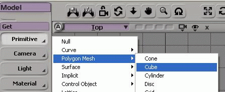 Get a cube
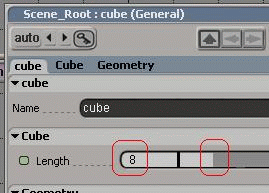 Edit cube property
Some more navigation tips in XSI
You probably can't see the entire cube in any of the views. Position the mouse pointer over the cube in the Camera view and press "F" to frame the selected object in that view. Position the mouse pointer somewhere inside the Top view window (the view at the upper left) and press "F" to frame the cube in that view. With the pointer inside any of the views over your object, press shift-F to frame the object in all views.
 View buttons
LMB the little "B" button to hide the other views. The windows are still there but nothing is shown. LMB the "B" button again to restore all four views.
RMB the "B" button to toggle mute and solo. mute hides the view and restores it. solo hides the other three views and restores them.
LMB the button labeled Camera with the little downarrow to popup a menu of the various views you can select for that view window. Without selecting anything from the popup menu, LMB somewhere other than on the menu to make the popup menu disappear.
LMB the little camera icon to popup a menu of the various tools we can use in this view. We'll use some of those tools later. I call this the navigation tool or navtool menu.
LMB the "x" icon to toggle the camera's view from whereever it's currently pointed, to a view along the x axis of the scene. LMB the button again to return to the previous view.
LMB the Wireframe pulldown menu button to see the various types of camera views (and other options) you can select. We'll be using this menu later when we texture the cube to make our model look better.
LMB the "box within a box" at the far right to toggle the camera view from one-of-four-views to full view. LMB again to restore the four view layout. This is similar to the normal Windows maximize and restore functions.
Position the mouse pointer over the camera view and press "o" (the letter oh) to select the orbit tool. When this tool is selected (note how the mouse pointer looks), you can LMB drag to move the camera around the cube freely while maintaining the camera's center of view.
When using the orbit tool, RMB drag constrains the camera movement in the vertical direction.
MMB drag constrains the camera movement in the horizontal direction.
You can toggle the orbit tool on and off by pressing "o" again. You can toggle any of the navigation tools this way. You can also select any of these tools from the camera icon dropdown menu, the navtool menu or with a hotkey as indicated in the menu.
Remember: the mouse pointer must be over the view for which you want to use the tool!
With the pointer over the camera view, press "p" to select the dolly tool (or select it from the navtool menu). When this tool is selected, you can LMB drag to dolly the camera back and forth to change the view. MMB dragging and RMB dragging dolly the camera back and forth at different rates.
With the pointer over the camera view, press "z" to select the pan tool. When this tool is selected, you can LMB drag to move the camera in the horizontal and vertical directions without staying centered on the object. RMB dollies the camera back automatically. MMB dollies the camera forward automatically.
A few more buttons (Yeah, I know, more buttons. We'll get to the modeling in a moment)
 Select tool buttons
The first button on the left is the object select button. This button is used to put the camera view into the object select mode. To use it, LMB the object select button and LMB drag over a portion of an object in the camera view to select that object for manipulation.
To deselect objects, LMB drag in the camera view over a portion of the view where there are no objects.
LMB the object select button and LMB drag in the camera view away from the cube's wireframe. The cube will turn to a black wireframe to show that it's not selected. LMB drag over any part of the cube's wireframe to select it. The cube turns to a white color to show it's selected.
We won't be using the next two buttons in the camera view in this tutorial. You'll learn more about them in later XSI tutorials.
The last two buttons are the undo and redo buttons. You can use ctrl-z to undo as well.
Get a texture to apply to our model
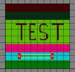
In the next section of this tutorial, you'll apply a texture that looks like the texture below to your cube model. Yeah, it's pretty basic but it'll serve to learn basic texture mapping of a model in XSI.
 Test Image
Textures applied to Half-Life 2 models must be in the targa format, an image file with the extension .tga.
Setup the texture to apply to your model
Make sure the cube object is selected. If needed, LMB the object select button and LMB drag a part of the cube to select it (the wireframe turns white).
With the cube selected, go to the Render item in the main menu and LMB Render->Get-Texture->Image. When asked to save local copies of materials, answer Yes.
What you see in the Scene Material dialog box that pops up is the default texture that XSI selects. You want to use the testimage.tga file you downloaded. LMB the Edit button to the right of the Image property where it says "noIcon_pic."
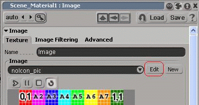 Scene property box
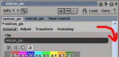 Scroll down
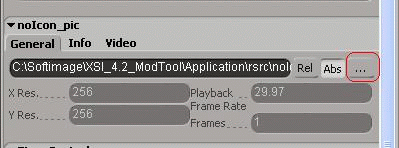 Change texture
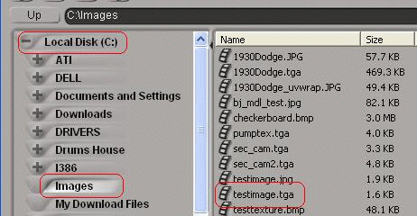 Pick texture in folder
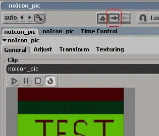 Back to the scene material
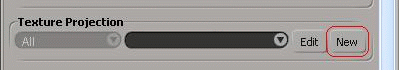 Get a new projection
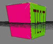
In the camera view, LMB the pulldown list which should currently be labeled Wireframe and select Textured Decal from the list. You should now see that the texture has been applied to our model cube.
With the mouse pointer over the camera view, press "o" (select the orbit tool) and look your model over. Because you chose a cubic mapping for the texture, the entire texture has been applied to each face of the cube.
At this point, you could export the Source files necessary to compile a model. However, model texturing normally involves applying just portions of the texture to different parts of the model.
Getting Ready to UV Map the model
The term "uv mapping" means to select portions of a texture to apply to individual polygons making up the model. It's not particularly important to understand "uv coordinates" to texture map your model. XSI does it all graphically. Those are terms you will see, however, in articles and tutorials around the Web if you want to search for more information.
As a goal, let's map just the word "Test" to just one face of the cube and map different solid colors to the other fives faces of the cube. To do this, you'll select one face of the cube at a time and adjust the texture projection for just that face to the portion of the texture you want.
Texture mapping is most easily done using the Texture Editor in XSI. Press alt-7 (hold down the alt key and the 7 key on the main keyboard at the same time) to bring up the Texture Editor. If you need to, LMB drag the title bar of the Texture Editor window (labeled, of all things, Texture Editor) to move the editor window down to the bottom half of the screen. You want to be able to see most of the model in the camera view and most of the texture layout in the Texture Editor. Even with the texture editor (tex-ed) window showing, you can position the mouse pointer over the camera view and use the navigation tools in the camera window to make adjustments.
You can also resize the tex-ed window (as you would most Windows windows) by moving the mouse pointer over an edge of the window (top, bottom, left or right edges) until the mouse pointer turns into a right-left arrow or an up-down arrow pointer. LMB drag the tex-ed to a suitable size. You can use the pan tool ("z") in the tex-ed to adjust your view of the texture and texture projection polygons. With the pan tool selected, you can LMB to zoom out; MMB to zoom in; and RMB drag to move the image in the window up-down and left-right. Press "z" again to go back to the arrow mouse pointer.
Texture Editor Buttons (sigh, more buttons)
Depending on your screen width and the tex-ed window width, your buttons may not be in exactly the same arrangement as shown below. However, they're all there at the top of the tex-ed window. Locate them and read the description of each. We'll be using these buttons a lot!
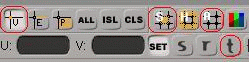 Text Editor buttons
 Vertex mode button
 Show-selected button
 Show-all button
 Texture Editor translate button
So, LMB the tex-ed vertex button (the first button shown above, the one with the "v" and the two crossing lines in it) to make sure the tex-ed is in the vertex mode.
Now, about the important sequence I mentioned in the description of the show-selected button above. XSI seems a bit finicky about the order you select cube vertices and show the selection in the tex-ded.
The following sequence ensures that the texture selection polygon in the tex-ed matches the face you've selected in the camera view. If you get into a situation where you don't see what you expect in the tex-ed, follow this sequence to get yourself straightened out again.
- LMB the show-all button in the tex-ed.
- LMB the face select button in the camera view.
- With the mouse pointer over the camera view, press ctrl-shift-A. It's awkward, I know. As an alternative, in the main menu above the camera window, LMB the Select menu item and select "Deselect All." That may be a little easier. This will deselect any currently selected faces in the camera view.
- LMB the face select button in the camera view. (Review the button descriptions in the A Few More Buttons.. section of the tutorial above if needed.)
- LMB the desired face of the cube you want to texture.
- LMB the show-selected button in the tex-ed.
Texture Mapping the Cube (finally)
At this point, you may want to save your work. In the main menu, LMB File->Save and pick a filename. You may as well save your file in the default directory.
In the camera view, make sure the cube is selected. Using the "important" sequence above, select one of the faces of the cube. It doesn't really matter which one.
To make sure you've selected just one face of the cube, change to Wireframe in the camera view, select the orbit tool and move the camera around to see that just one face of the cube is highlighted. Deselect the orbit tool.
You can switch back and forth between Wireframe and Textured Decal displays in the camera view, as desired, to make face selection easiest for you. Face selection works the same in either display mode.
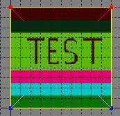
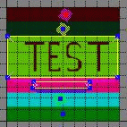
The tex-ed may not seemed to have changed a lot, but it shows four selected vertices (they're red instead of blue normally) connected by lines. This four-sided polygon is the texture selection polygon for the face you have selected in the camera view.
As stated above, part of our goal is to map just the word "Test" onto one face of the cube. The following steps will move the polygon in the tex-ed around to do that.
With the mouse pointer over the tex-ed, make sure the mouse pointer is an arrow. If it's not, press "v" (toggling in and out of translate) until the pointer turns to an arrow.
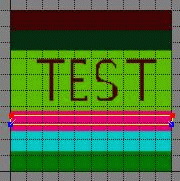
In the vertex mode with the mouse pointer as an arrow, you can select vertices. MMB drag the bottom two vertices in the tex-ed to deselect them. There should be two red vertices (selected) at the top of the polygon and two blue vertices (unselected) at the bottom of the polygon.
 Select top vertices
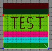 Move top vertices
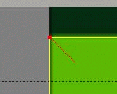 Pan in
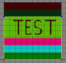 Select bottom vertices
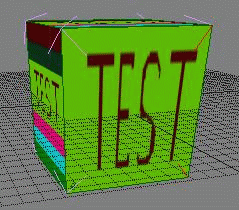 A face is textured
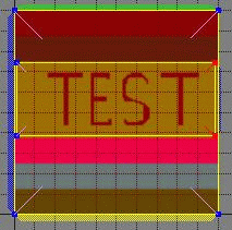 Show-all with first face textured
Follow the important sequence of steps to select another face of the cube. If needed, use the navtools in the camera view to show a face to click on. Use either the Wireframe or Textured Decal display, whichever suits you.
The tex-ed should show a polygon covering the entire texture. Using the techniques you learned mapping the "Test" portion of the texture to a face, adjust the polygon so that it covers only the portion of the texture with the bright pink color.
 Second face in pink
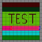 Left vertices moved to the right
Select just the two vertices on the right and translate them to the left a little. In the camera view, you should now see that the face you selected is entirely covered with a shocking pink color.
 Pink textured face
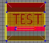 Show-all two faces textured
With one of the faces mapped to a solid color, select all the vertices.
 Third face mapped to blue
 Texture Editor collapse button
 Vertices collapsed
Now test what you've learned. One by one, select the other faces of the cube and map them each to a different color. You can use either the polygon technique we used for the pink color or the collapse-to-point technique you just learned. You may have to use the navigation tools (orbit, pan, dolly) in the camera view to select the various faces of the cube.
 Show-all all faces mapped
Exporting smd files
Having created the geometry (the cube) for your model and having textured it, you're almost ready to export your reference smd file to be compiled into a Half-Life 2 model.
In the main menu, LMB the ValveSource menu item and select Export smd... In the save file dialog box that opens up, make sure Model (.SMD) is selected in the pulldown box under Options, File Type as shown below. LMB the button labeled "..." to bring up the filename box.
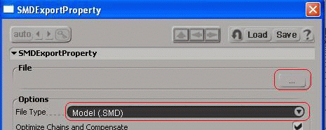 smd export dialog
In the Filename edit box at the bottom of the filename dialog, type in a name for your smd file. In this case, just call it "box" and LMB OK to close the filename dialog.
LMB OK to close the SMDExportProperty box and save your model file as "box.smd" in the models folder. Because this model will be used only as a prop_static in your HL2 map, you don't need any other smd files. In a later tutorial on creating an animated HL2 model for use as a <ent>prop_dynamic, you'll need to export additional files.
Congratulations, you just created an smd file for your textured box model!
Reference the HL2 Modeling Setup tutorial to compile your texture and smd files for use as a prop_static in Hammer.
This may have seemed like a long, complicated procedure to create your model. However, once you've been through it just a couple of times and know which buttons to click and which mouse buttons to use for selection and translations, you'll find you can create a new model from scratch easily and quickly. I'm still an amateur using the XSI Mod Tool, but, in writing this tutorial, I created several simple cube models, textured them and exported the SMD file in just minutes!
- Categories
- Tutorials
- Intermediate Tutorials
- Modelling
- Source Tutorials
- Article Credits
-
 BJ
–
Original author
BJ
–
Original author
4 Comments
You must log in to post a comment. You can login or register a new account.
Also, when i select a face of the cube and then click the Show Selected button in the TexEd, only 3 vertices are selected (red) and 1 is unselected, while i clearly see that the entire face is selected.
And when i move the blue unselected face, the texture shifts properly on that selected face of my cube. But when is select and move one of the other 3 vertcies that were selected in the first place, then the texture on the other unselected faces shift as well!
That way i never get the cube correctly texture, because when i finish uv mapping one face, the texture on another face on the cube i previously uv mapped correctly, is all screwed up again!
I hope this makes sense, if not, ill record a video.
I don't want two meshes, i just want the cube texture correctly, have 5 faces one color (from that texture included in this tutorial) and 1 faces with only the TEST word. I can't get that to work because XSI selects only 3 vertices instead of 4.