Tutorial: Detailing map brushes using XSI Last edited 5 months ago2024-09-20 21:56:46 UTC
This tutorial, in step-by-step details, will show you how to:
1. Create your brushwork
The 1st thing that you will need is some sort of reference brushwork to import into XSI. For this tutorial, I will be using my least favourite thing to make in Hammer: stairs. I have created a very basic version of them.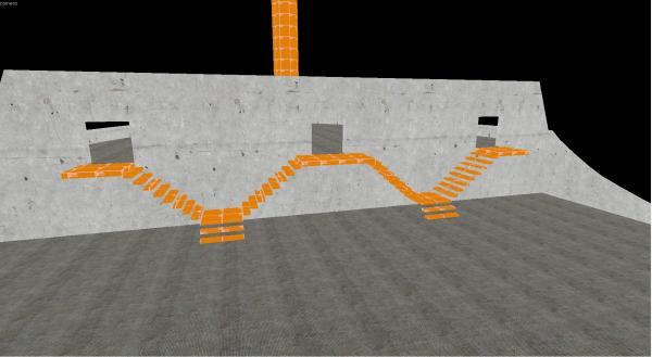 Hammer Brushwork
You will then need to create a prefab from the brushes you want to export. Select the appropriate brushes, then press Ctrl + R or use the drop down menu in Tools.
Hammer Brushwork
You will then need to create a prefab from the brushes you want to export. Select the appropriate brushes, then press Ctrl + R or use the drop down menu in Tools.
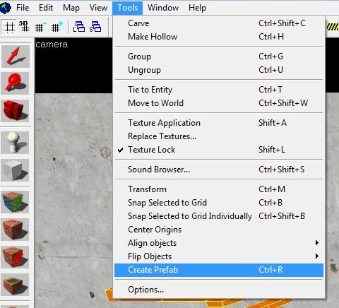 Create Prefab
The default folder it will save to is:
Create Prefab
The default folder it will save to is:
 Folder
*Note: If you are not using Orange Box configuration, then it will be in SourceSDK/bin/prefabs
Folder
*Note: If you are not using Orange Box configuration, then it will be in SourceSDK/bin/prefabs
2. Importing into XSI Mod Tools
Now that you have your prefab created, and you know its location, you are ready to bring it into XSI.
Go to the ValveSource toolbar, and select VMF Tools -> Import VMF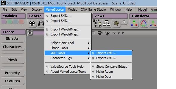 Import the VMF
A new window will appear where you specify the location of the prefab file. Don't worry about importing a texture, as you will have to re-texture things later. Be sure to uncheck the import materials box.
Import the VMF
A new window will appear where you specify the location of the prefab file. Don't worry about importing a texture, as you will have to re-texture things later. Be sure to uncheck the import materials box.
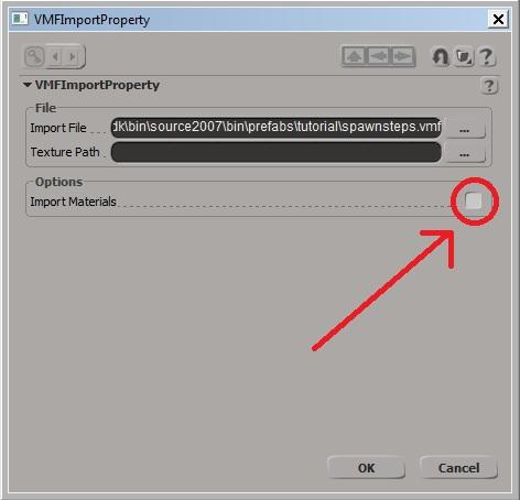 Uncheck Import Materials
Now you have the brushwork in XSI, but you most likely can't see it yet.
Uncheck Import Materials
Now you have the brushwork in XSI, but you most likely can't see it yet.
3. Configuring XSI Mod Tools
Now we will be changing how movement behaves in XSI to get our brushwork centered.
First, we need to go into the visibility options by either using Shift + S or by using the menu bar inside your perspective viewport.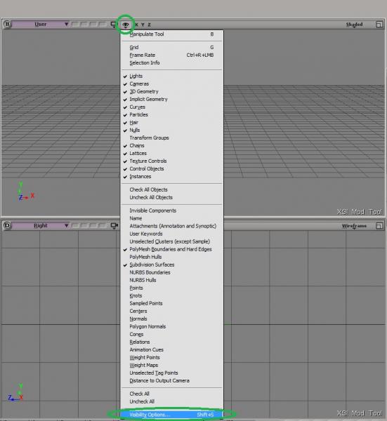 Visibility Toolbar
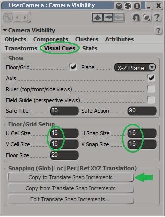
Make the following changes, then hit Copy to Translate Snap Increments
Visibility Toolbar
Make the following changes, then hit Copy to Translate Snap Increments
 Picture
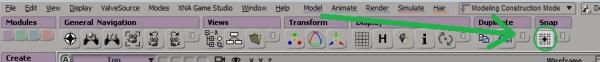
Now we will turn on the Snap setting so that brushes snap to the grid, like in Hammer.
Picture
Now we will turn on the Snap setting so that brushes snap to the grid, like in Hammer.
 Picture
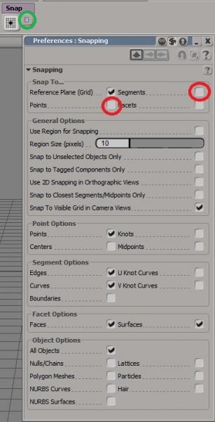
Now we need to make sure that things only snap to the grid. Click the button next to snap and unselect Points and Segments
Picture
Now we need to make sure that things only snap to the grid. Click the button next to snap and unselect Points and Segments
 Picture
Now that we have our object in the workspace, and the grid configured, we need to move our objects to the middle.
Picture
Now that we have our object in the workspace, and the grid configured, we need to move our objects to the middle.
*Note: Pressing 'A' while in a window will center 'ALL' in your viewport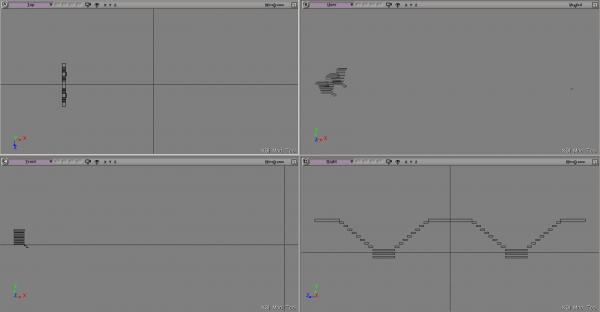 Picture
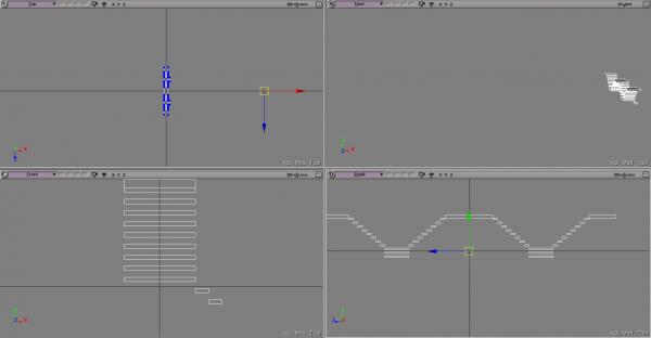
Press V to bring up the translate widget and move along the X axis to center your object
Picture
Press V to bring up the translate widget and move along the X axis to center your object
 Picture
Once you have your object centered, you need to remove the default origin that XSI has assigned to your object. To do this, we will need to remove the map root these brushes are attached to.
Picture
Once you have your object centered, you need to remove the default origin that XSI has assigned to your object. To do this, we will need to remove the map root these brushes are attached to.
With all of your brushes selected, hit the number 8 to open the Tree.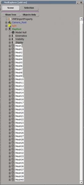 Picture
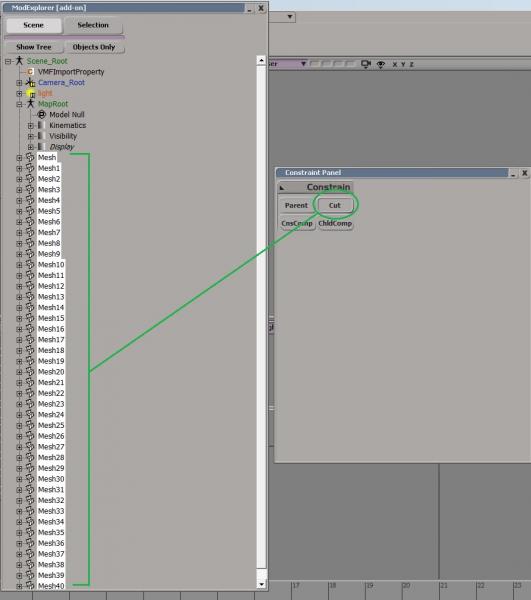
Holding Shift, you can select all the meshes under the MapRoot. Then, open your Constraint Panel and hit Cut.
Picture
Holding Shift, you can select all the meshes under the MapRoot. Then, open your Constraint Panel and hit Cut.
 Picture
*Note: If you do not have a Constraint Panel, right-click under Freeze History and you can add it in the Customize menu.
Picture
*Note: If you do not have a Constraint Panel, right-click under Freeze History and you can add it in the Customize menu.
Select all objects by either dragging your mouse around them all, or by clicking the All button on the top right. Now right-click Transform and click Freeze All Transforms.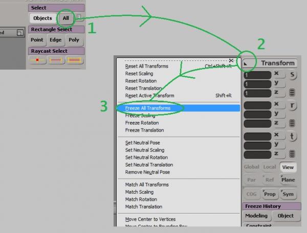 Picture
*Note: As a good measure, I also click the Freeze History; Modeling and Object buttons.
Picture
*Note: As a good measure, I also click the Freeze History; Modeling and Object buttons.
Now Delete the MapRoot and now your object has its own Center of Gravity.
4. Adding new items
For this tutorial, I will be adding a railing for the steps.
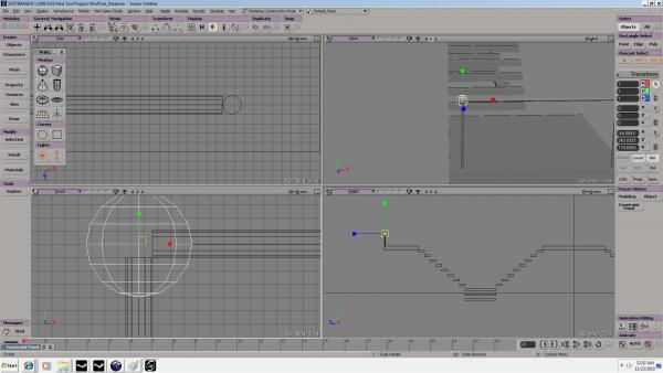
First, hit the Objects Button and select the cylinder option. In order to show you multiple ways of optimizing your work, I have unchecked the Close bottom end at this stage of development. This will make the bottom of the tube empty.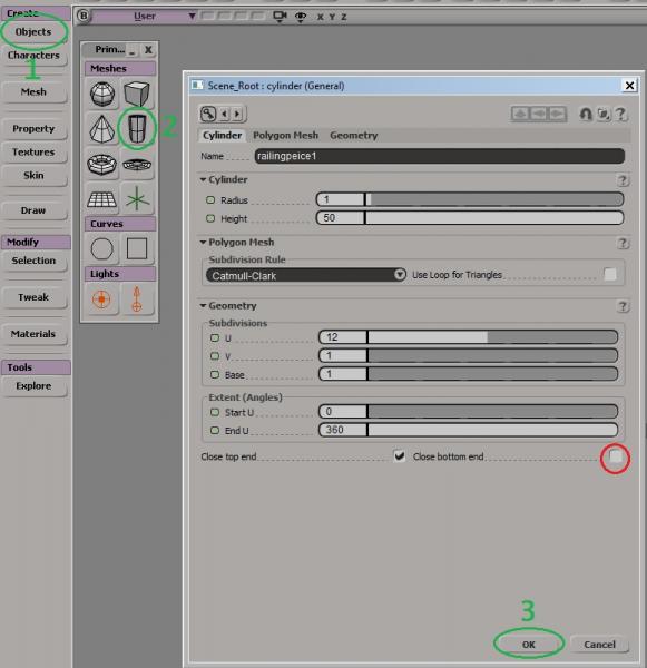 Picture
*Note: Removing faces is the easiest way to reduce triangles from your model.
Picture
*Note: Removing faces is the easiest way to reduce triangles from your model.
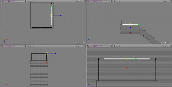
Using V to translate (move), position the 1st pipe in a corner of the platform. Be sure to check all viewports to make sure you are positioned correctly.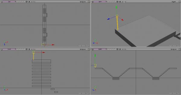 Picture
Now I will remove the top faces of this pipe, since they will not be visible.
Picture
Now I will remove the top faces of this pipe, since they will not be visible.
Select the Ray Cast Polygon selector and while holding the LMB down, sweep around the top to select the faces.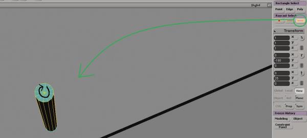 Picture
*Note: You could have achieved the same result by unchecking Close top end in the cylinder build tool dialog
Picture
*Note: You could have achieved the same result by unchecking Close top end in the cylinder build tool dialog
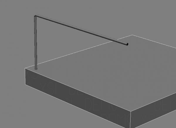
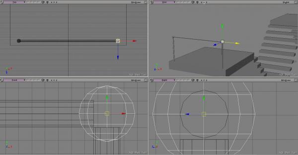
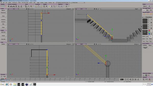
Now duplicate the brush by pressing Ctrl + D then press V to translate up. C will open the rotate tool, and by holding Shift, you will snap at perfect angles. Rotate to a 90 degree angle.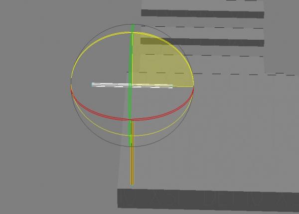 Picture
Move it into the middle of the platform. Press X to open the scaling tool and pull on the axis you want to extend.
Picture
Move it into the middle of the platform. Press X to open the scaling tool and pull on the axis you want to extend.
 Picture
*Note: You can also enter in exact values for any transformation on the right side of the screen. I use them to clean up my transforms.
Picture
*Note: You can also enter in exact values for any transformation on the right side of the screen. I use them to clean up my transforms.
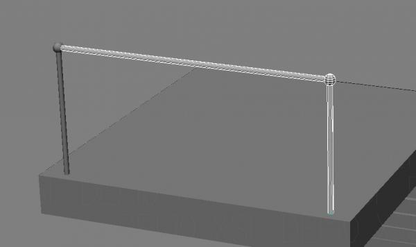
Now duplicate the 1st post and translate it over so you have a perfect edge on both sides of the middle bar. See the lower left view in the following image to see what I mean.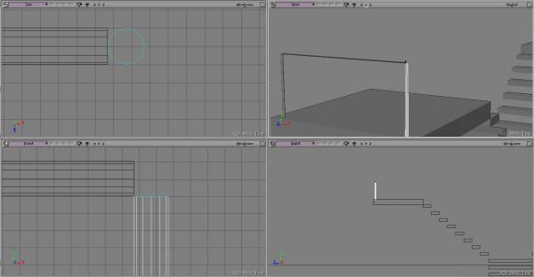 Picture
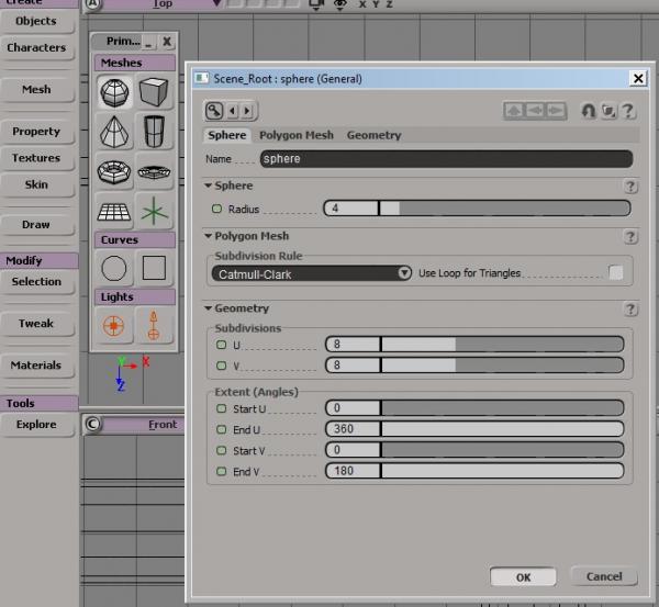
I want a nice ball on the top of my post to connect all my pieces. Open the Objects panel and select the sphere. I am using the default settings for this item.
Picture
I want a nice ball on the top of my post to connect all my pieces. Open the Objects panel and select the sphere. I am using the default settings for this item.
 Picture
V to translate it to the top of the post. It is a little too big so I want to scale the entire sphere down. To do this I will use x to scale while holding down Shift. This will scale it evenly on all sides.
Picture
V to translate it to the top of the post. It is a little too big so I want to scale the entire sphere down. To do this I will use x to scale while holding down Shift. This will scale it evenly on all sides.
 Picture
Position it in the middle and duplicate it Ctrl + D to the other side.
Picture
Position it in the middle and duplicate it Ctrl + D to the other side.
 Picture
Now to move multiple items at once. Select the outmost post, the sphere, and the top post then duplicate it (Ctrl + D).
Picture
Now to move multiple items at once. Select the outmost post, the sphere, and the top post then duplicate it (Ctrl + D).
 Picture
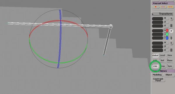
Move the selection away from the original and press C to turn on the rotate tool. Press the COG button to rotate all the objects around a central axis point. Rotate 90 degrees.
Picture
Move the selection away from the original and press C to turn on the rotate tool. Press the COG button to rotate all the objects around a central axis point. Rotate 90 degrees.
 Picture
Fix the middle bar to fit if needed by using X.
Picture
Fix the middle bar to fit if needed by using X.
 Picture
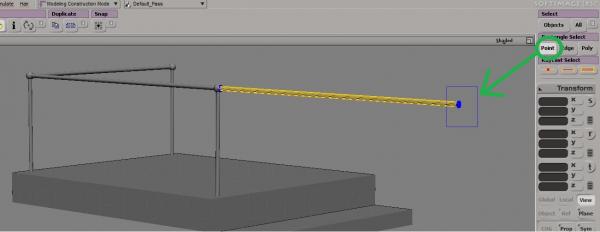
Now duplicate that bar and translate it out past the newest post. With the post selected, click the Point option under the Rectangle Select area. Now drag a square around the end of the post.
Picture
Now duplicate that bar and translate it out past the newest post. With the post selected, click the Point option under the Rectangle Select area. Now drag a square around the end of the post.
 Picture
Hit V to translate it down and out.
Picture
Hit V to translate it down and out.
 Picture
*Note: You can move on 2 axis by highlighting the box by the movement tool in one of the orthographic views.
Picture
*Note: You can move on 2 axis by highlighting the box by the movement tool in one of the orthographic views.
Duplicate any items you want to detail your new object.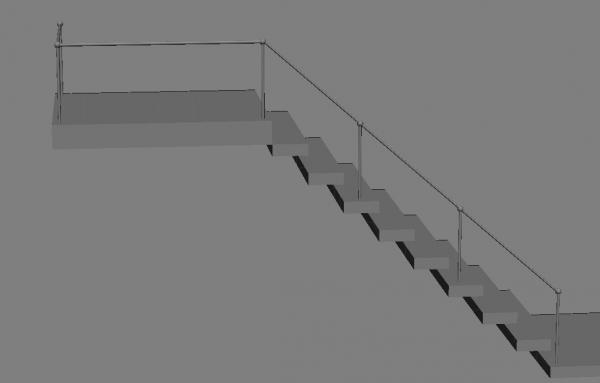 Picture
Duplicate and rotate as needed to finish up.
Picture
Duplicate and rotate as needed to finish up.
 Picture
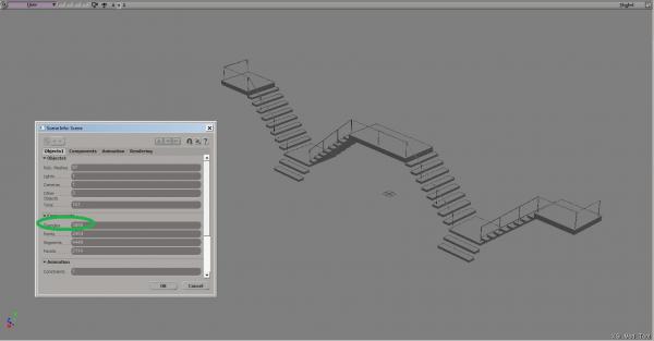
*Note: Hitting Alt + Enter will show you the budget for your model.
Picture
*Note: Hitting Alt + Enter will show you the budget for your model.
Go ahead and add any additional details you would like to your creation. Then continue to Page 2.
Now that you are finished building your model, we will start texturing it. You will notice that I've added extra detail to my object, so it will look a little different.
5. Texturing your model
Select an object for texturing by clicking on it. Now open the Texture menu and click Add -> Image.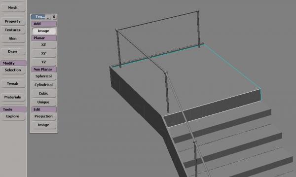 Picture
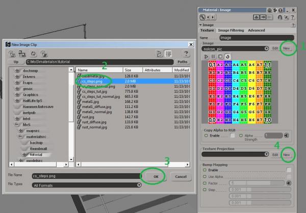
A new dialogue box will pop up. Click New to select an image for texturing with. After selecting it for the first time, it will appear in the drop down menu. Then, under Texture Projection, click New then Unique UV Mesh.
Picture
A new dialogue box will pop up. Click New to select an image for texturing with. After selecting it for the first time, it will appear in the drop down menu. Then, under Texture Projection, click New then Unique UV Mesh.
 Picture
Repeat this step until you have all areas covered.
Picture
Repeat this step until you have all areas covered.
 Picture
*Note: You can texture multiple pieces at the same time as long as they use the same texture.
Picture
*Note: You can texture multiple pieces at the same time as long as they use the same texture.
*Tip: Click Projection in the Texture tool tab to move, scale, and rotate the texture.
6. Creating a single Polymesh for export
In order for our model to turn out correctly, we must first turn all the separate objects into a single mesh. Start by dragging a box around all objects in the workspace.
Now click the Mesh button, then click Merge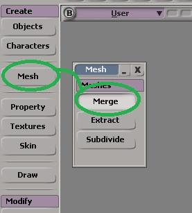 Picture
Now hit 8 to open your tree and F to find the object you have selected, the new polymesh. I choose to rename this, since we will be making a couple different meshes.
Picture
Now hit 8 to open your tree and F to find the object you have selected, the new polymesh. I choose to rename this, since we will be making a couple different meshes.
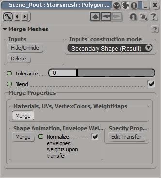
Click on Tolerance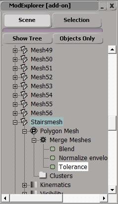 caption
then move the slider to , check Blend and click Merge under the Materials, UVs, Vertex, etc.
caption
then move the slider to , check Blend and click Merge under the Materials, UVs, Vertex, etc.
 Picture
You now have a single model made out of all of those objects, but have retained the original.
Picture
You now have a single model made out of all of those objects, but have retained the original.
*Note: Be sure to select all objects and freeze before doing anything!
Now, in the tree, select all objects except your new mesh and hit H to hide them. We will need them later to create the 2nd mesh.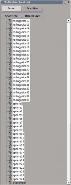 Picture
*TIP: Use the Raycast Polygon Select tool to pick and delete unseen faces to optimize your mesh
Picture
*TIP: Use the Raycast Polygon Select tool to pick and delete unseen faces to optimize your mesh
7. Creating your collision mesh
Select the new mesh you created in your tree and press H to hide it for now.
Now that you have primary model, we need to get rid of some of the finer details to have a decent Vphysic hitbox for source. I removed all of the posts and spheres, along with all of the other small details I added.
Then using the create tool, make very simple geometry to block off the areas you need.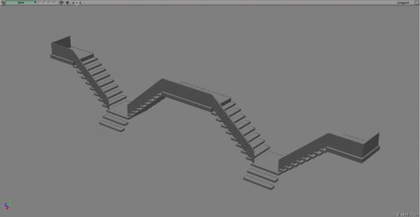 Picture
*Note: you have to give the collision mesh a texture, just use unique uv for the mesh and use any texture. It will not export without a texture.
Picture
*Note: you have to give the collision mesh a texture, just use unique uv for the mesh and use any texture. It will not export without a texture.
*Note: These will block all movement and shots, but not light
Now we will make the collision mesh, but in a different way that yields the same results.
Select all visible objects in the workspace. On the tools tab, click Model->Create->Poly. Mesh->Merge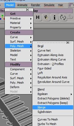 Picture
This will take you directly to the tolerance dialogue box where you will use the same settings as earlier.
Picture
Be sure to select all objects again and freeze them.
Picture
This will take you directly to the tolerance dialogue box where you will use the same settings as earlier.
Picture
Be sure to select all objects again and freeze them.
Continue to Page 3 for exporting and compiling for use in your map.
We now have two meshes: one is a visual representation of out model and the other is a simplified physical barrier. We will now export these models and get them ready for use in your map.
8. Exporting from XSI
Open the tree and hide everything except the first mesh you made that represents the model.Picture
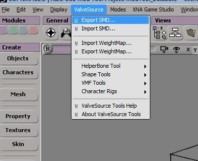
Now click ValveSource->Export SMD...
 Picture
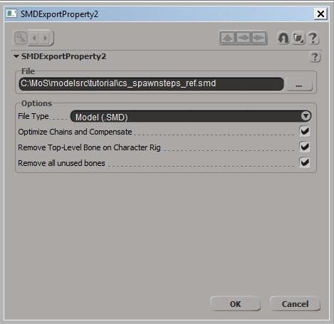
Save to the desired location, but give it the name mymodel_ref.smd and under File Type, pick Model(.SMD).
Picture
Save to the desired location, but give it the name mymodel_ref.smd and under File Type, pick Model(.SMD).
 Picture
This is the primary model file, so now let's export the physical collision mesh.
Picture
This is the primary model file, so now let's export the physical collision mesh.
Open up the tree again and hide everything except the collision mesh.
IMPORTANT
Collision meshes have to be very simple and have only one smoothing group. To make sure this is the case, you will need an advanced feature. This requires changing the view mode we are in.
On the main tool bar, click View->Layouts->Default.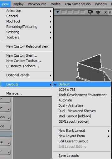 Picture
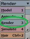
Then switch to the Render mode...
Picture
Then switch to the Render mode...
 Picture
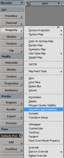
...and then with the mesh selected, Click Property->Geometry Approximation.
Picture
...and then with the mesh selected, Click Property->Geometry Approximation.
 Picture
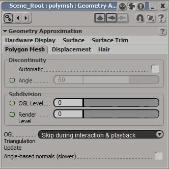
Navigate to Polygon Mesh and uncheck Automatic in the Discontinuity section. This will remove all hard edges.
Picture
Navigate to Polygon Mesh and uncheck Automatic in the Discontinuity section. This will remove all hard edges.
 Picture
Now click ValveSource->Export SMD...
Picture
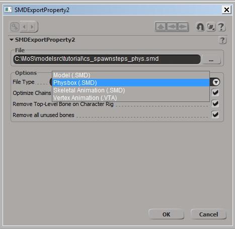
This time we will make a couple changes. Change the save name to mymodel_phys and the File Type to Physbox(.SMD).
Picture
Now click ValveSource->Export SMD...
Picture
This time we will make a couple changes. Change the save name to mymodel_phys and the File Type to Physbox(.SMD).
 Picture
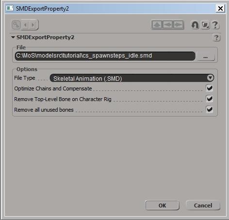
Now Export one more time, but change name to mymodel_idle and change File Type to Skeletal Animation(.SMD)
Picture
Now Export one more time, but change name to mymodel_idle and change File Type to Skeletal Animation(.SMD)
 Picture
*Note: It does not matter what you export as the animation if this is a static prop.
Picture
*Note: It does not matter what you export as the animation if this is a static prop.
9. Compiling your model
Place the material files you have created from the textures you used on your model in a directory of your choice.
Place the 3 .SMD files you have created in a directory of your choice.
Create your .QC file.
This is done using a basic text editor. I will include my .QC file for you to use as a template if you wish, or you can create one yourself.
The first line is the name and location of the model you are going to create.
$modelname "propsmapitemsmymodel.mdl
The next line will be the reference mesh you created...
$body mybody "mymodel_ref.smd"
...followed by the type of model you are creating.
$staticprop
Then the surface properties of your model. A list of these can be found here.
$surfaceprop Metal
Now, add the location of your materials. The default folder is materials, so use everything after that in the directory structure.
$cdmaterials "models"
*Note: the above directory is equal to modnamematerialsmodels
Now add the animation .SMD
$sequence idle "mymodel_idle" loop fps 15
The only part you may need to edit beyond your file name. Collision models have a default max objects of 30 and for most models that is enough. For larger models like the one we have created here, you will need more than that.
*Note: You will know if your model uses more than the default if the collision box fills your model instead of sticking to it like shrink wrap.
$collisionmodel "mymodel_phys" {concave}
I had to change mine to a larger number. You want to avoid this whenever possible, but it can't be helped on larger models.
This is how you change it to add more:
$collisionmodel "cs_spawnsteps_phys" { $concave $maxconvexpieces 50 }
Now save your file in the same folder your SMD files are in. Be sure to make the extension .QC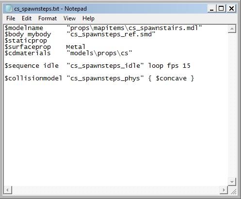 Example .QC file
Now you need to run your .QC file. I use GUIStudioMDL for this, but you may have your own alternative.
Example .QC file
Now you need to run your .QC file. I use GUIStudioMDL for this, but you may have your own alternative.
The first step is to select the proper SDK version you are using, then pick or add the mod you are making the model for.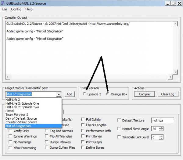 GUIStudiomdl
Click Load QC File... and navigate to your .QC file.
GUIStudiomdl
Click Load QC File... and navigate to your .QC file.
Click compile and hopefully you won't get any errors.
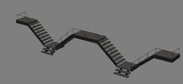
After it compiles, you can use model viewer to check it out or put it in your map.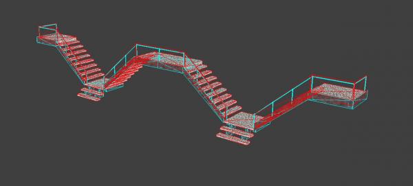 Wireframe and Collision wireframe
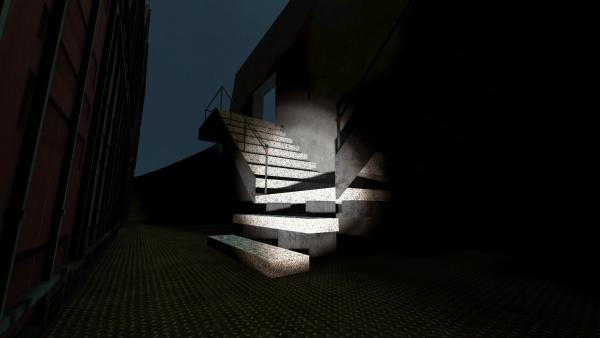 In Game
Additional resources
In Game
Additional resources
VDC XSI tutorials
Noesis Interactive Video tutorial on XSI navigation
VTF Edit - GUI material editor
- Take a brush, or series of brushes out of Hammer
- Import it into XSI Mod Tools
- Configure XSI Mod Tools properly
- Create and manipulate new geometry
- Texture your model
- Create a single polymesh
- Create a collision mesh
- Export from XSI Mod Tools
- Compile your new model
- You have a general understanding of Hammer
- You know how to navigate XSI Mod Tools
- You have the Valve Source plug-in for XSI Mod Tools
- You are in the Mod Tools Layout for XSI
- You know how to create materials for use in Source
1. Create your brushwork
The 1st thing that you will need is some sort of reference brushwork to import into XSI. For this tutorial, I will be using my least favourite thing to make in Hammer: stairs. I have created a very basic version of them.
Hammer BrushworkCreate PrefabFolder2. Importing into XSI Mod Tools
Now that you have your prefab created, and you know its location, you are ready to bring it into XSI.
Go to the ValveSource toolbar, and select VMF Tools -> Import VMF
Import the VMFUncheck Import Materials3. Configuring XSI Mod Tools
Now we will be changing how movement behaves in XSI to get our brushwork centered.
First, we need to go into the visibility options by either using Shift + S or by using the menu bar inside your perspective viewport.
Visibility ToolbarPicturePicturePicture*Note: Pressing 'A' while in a window will center 'ALL' in your viewport
PicturePictureWith all of your brushes selected, hit the number 8 to open the Tree.
PicturePictureSelect all objects by either dragging your mouse around them all, or by clicking the All button on the top right. Now right-click Transform and click Freeze All Transforms.
PictureNow Delete the MapRoot and now your object has its own Center of Gravity.
4. Adding new items
For this tutorial, I will be adding a railing for the steps.
First, hit the Objects Button and select the cylinder option. In order to show you multiple ways of optimizing your work, I have unchecked the Close bottom end at this stage of development. This will make the bottom of the tube empty.
PictureUsing V to translate (move), position the 1st pipe in a corner of the platform. Be sure to check all viewports to make sure you are positioned correctly.
PictureSelect the Ray Cast Polygon selector and while holding the LMB down, sweep around the top to select the faces.
PictureNow duplicate the brush by pressing Ctrl + D then press V to translate up. C will open the rotate tool, and by holding Shift, you will snap at perfect angles. Rotate to a 90 degree angle.
PicturePictureNow duplicate the 1st post and translate it over so you have a perfect edge on both sides of the middle bar. See the lower left view in the following image to see what I mean.
PicturePicturePicturePicturePicturePicturePicturePicturePictureDuplicate any items you want to detail your new object.
PicturePictureGo ahead and add any additional details you would like to your creation. Then continue to Page 2.
Now that you are finished building your model, we will start texturing it. You will notice that I've added extra detail to my object, so it will look a little different.
5. Texturing your model
Select an object for texturing by clicking on it. Now open the Texture menu and click Add -> Image.
PicturePicturePicture*Tip: Click Projection in the Texture tool tab to move, scale, and rotate the texture.
6. Creating a single Polymesh for export
In order for our model to turn out correctly, we must first turn all the separate objects into a single mesh. Start by dragging a box around all objects in the workspace.
Now click the Mesh button, then click Merge
PictureClick on Tolerance
captionPicture*Note: Be sure to select all objects and freeze before doing anything!
Now, in the tree, select all objects except your new mesh and hit H to hide them. We will need them later to create the 2nd mesh.
Picture7. Creating your collision mesh
Select the new mesh you created in your tree and press H to hide it for now.
Now that you have primary model, we need to get rid of some of the finer details to have a decent Vphysic hitbox for source. I removed all of the posts and spheres, along with all of the other small details I added.
Then using the create tool, make very simple geometry to block off the areas you need.
Picture*Note: These will block all movement and shots, but not light
Now we will make the collision mesh, but in a different way that yields the same results.
Select all visible objects in the workspace. On the tools tab, click Model->Create->Poly. Mesh->Merge
PicturePictureContinue to Page 3 for exporting and compiling for use in your map.
We now have two meshes: one is a visual representation of out model and the other is a simplified physical barrier. We will now export these models and get them ready for use in your map.
8. Exporting from XSI
Open the tree and hide everything except the first mesh you made that represents the model.
PicturePicturePictureOpen up the tree again and hide everything except the collision mesh.
IMPORTANT
Collision meshes have to be very simple and have only one smoothing group. To make sure this is the case, you will need an advanced feature. This requires changing the view mode we are in.
On the main tool bar, click View->Layouts->Default.
PicturePicturePicturePicturePicturePicturePicture9. Compiling your model
Place the material files you have created from the textures you used on your model in a directory of your choice.
Place the 3 .SMD files you have created in a directory of your choice.
Create your .QC file.
This is done using a basic text editor. I will include my .QC file for you to use as a template if you wish, or you can create one yourself.
The first line is the name and location of the model you are going to create.
$modelname "propsmapitemsmymodel.mdl
The next line will be the reference mesh you created...
$body mybody "mymodel_ref.smd"
...followed by the type of model you are creating.
$staticprop
Then the surface properties of your model. A list of these can be found here.
$surfaceprop Metal
Now, add the location of your materials. The default folder is materials, so use everything after that in the directory structure.
$cdmaterials "models"
*Note: the above directory is equal to modnamematerialsmodels
Now add the animation .SMD
$sequence idle "mymodel_idle" loop fps 15
The only part you may need to edit beyond your file name. Collision models have a default max objects of 30 and for most models that is enough. For larger models like the one we have created here, you will need more than that.
*Note: You will know if your model uses more than the default if the collision box fills your model instead of sticking to it like shrink wrap.
$collisionmodel "mymodel_phys" {concave}
I had to change mine to a larger number. You want to avoid this whenever possible, but it can't be helped on larger models.
This is how you change it to add more:
$collisionmodel "cs_spawnsteps_phys" { $concave $maxconvexpieces 50 }
Now save your file in the same folder your SMD files are in. Be sure to make the extension .QC
Example .QC fileThe first step is to select the proper SDK version you are using, then pick or add the mod you are making the model for.
GUIStudiomdlClick compile and hopefully you won't get any errors.
After it compiles, you can use model viewer to check it out or put it in your map.
Wireframe and Collision wireframeIn GameVDC XSI tutorials
Noesis Interactive Video tutorial on XSI navigation
VTF Edit - GUI material editor
- Categories
- Tutorials
- Modelling
- Advanced Tutorials
- Source Tutorials
- Article Credits
-
 Don Punch
–
Original author
Don Punch
–
Original author
3 Comments
You must log in to post a comment. You can login or register a new account.
)
1) When i tried to freeze my geometry, it crashed my XSI and gave me a mass of gibberish chinese text. I tried reinstalling but that didnt work, so i just made a barrel and exported per the rest of the instructions.
Worked fine except:
2)I am doing a model for HL2:EP2. I have my texture; barrel.png in the models folder, but when i load into hammer/game i get the checkerboard texture. I dont get any compile errors, and half life isnt giving me any errors in console relating missing texture... Any idea as to what i can be doing wrong?
Fantastic tutorial nonetheless. Best one i've followed!!