VERC: MAP File Format Specification Last edited 1 year ago2023-08-26 07:32:04 UTC
The MAP format is a widely used format, and the one accepted by the compilers. It's also a text format, meaning that it's easy for people to mess around with - but they can only do this if they know what everything does. Previous articles on the subject refrained from going into the gory details in many parts - especially texturing. This article aims to rectify that, and provide the full and complete MAP format for all to see.
What people often get confused about is that a Half-Life map (or any Quake engine-based map, for that matter) is entirely entities. However, for simplicity, the main world geometry is often referred to as not being an entity; this is, technically, wrong. Anything that isn't tied to an entity is part of the entity called "worldspawn" - remember this.
Why'd I just tell you that? Well, the MAP format is organised into entities. Everything is defined by entities - including the world, in the "worldspawn" entity. Let's take a look at how a basic entity is defined:
Let's examine exactly how brushes get defined. (When talking about a 'line', I'll be referring to the lines of text in the definition of a brush.) Every line defines one plane (a plane is an infinitely thin, infinitely big 'sheet' in 3D space) which, essentially, defines one face. To get the actual faces of the brush, the area contained within all the planes put together is used.
To define one actual plane, three points must be given (shown by x1, y1, z1, x2, y2, z2 and x3, y3, z3). They must be in a clockwise order when facing the outside of the plane - that is, the side that points outwards from the brush, and these points must lie on the surface of the plane. They must also be different from one another, and not lie on a line - they must form three corners of a triangle when joined up. (Three vertices of the face being represented by this plane will often suffice.)
After those three points, it's all defining how the face residing on that plane will be textured. First up is fairly self-explanatory - the texture name - but the next part is fairly difficult to both explain and to grasp. To define the orientation of textures, a pair of axes are used. These define what is "flat" for that face's texture space. If you picture a flat plane covered in the texture, with the two axes lying flat on that plane, that's the texture's plane. This is then flattened right onto the plane of the face. This means that if you want the texture to be perfect scale on the face, the axes need to define a plane that is parallel to the face's plane, otherwise you'll get stretching.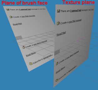 The texture plane (on the right) 'flattened' onto the actual face (left) - notice how it gets stretched on the face.
These axes are defined by tx1/y1/z1 and tx2/y2/z2, giving two vectors which define what's "right" and what's "up" relative to the texture - so if you wanted to go "right" 1 unit, you'd go along the first axis for 1 unit. Going "down" 2 units would be going backwards along the second axis for 2 units. How much the texture is offset along these axes is defined by toffs1 and toffs2, measured in HL units.
The texture plane (on the right) 'flattened' onto the actual face (left) - notice how it gets stretched on the face.
These axes are defined by tx1/y1/z1 and tx2/y2/z2, giving two vectors which define what's "right" and what's "up" relative to the texture - so if you wanted to go "right" 1 unit, you'd go along the first axis for 1 unit. Going "down" 2 units would be going backwards along the second axis for 2 units. How much the texture is offset along these axes is defined by toffs1 and toffs2, measured in HL units.
The last three items are fairly simple, but rotation is a fairly weird one. Contrary to what you may think, it doesn't define how much the texture should be rotated; it defines how much it ALREADY HAS been rotated. This is so Worldcraft/Hammer can rotate the texture axes accordingly, and means that if you wanted to code a program to rotate the texture 45 degrees, you'd need to add 45 to rotation (so that WC/Hammer shows it being rotated 45) and rotate the two texture axes by 45 degrees too.
Luckily, scaleX and scaleY are both very simple; they define how much the texture is stretched along the two texture axes. Operation is the same as WC/Hammer - the larger the value, the more it's streched. Less than 1, and it's squeezed up; less than 0, and it's mirrored.
Having shown you all that, here's an example of a simple brush entity - a func_breakable:
There's one property I haven't mentioned yet, and that's
This is all the knowledge that's required to understand the MAP format, but as I said earlier, I will elaborate on worldspawn. Essentially, it's exactly the same as other brush entities (its properties can be edited by going to the Map menu and selecting Map properties in Hammer) except with a few extra properties that should be defined. Here's an example of a
And there you have it - the MAP format in a nutshell. Hopefully you can now see why concave brushes are impossible to represent in this format without creating two or more separate brushes, and you can now have fun creating programs to manipulate MAP files to your heart's content.
What people often get confused about is that a Half-Life map (or any Quake engine-based map, for that matter) is entirely entities. However, for simplicity, the main world geometry is often referred to as not being an entity; this is, technically, wrong. Anything that isn't tied to an entity is part of the entity called "worldspawn" - remember this.
Why'd I just tell you that? Well, the MAP format is organised into entities. Everything is defined by entities - including the world, in the "worldspawn" entity. Let's take a look at how a basic entity is defined:
{
    "classname" "entity_classname_here"
    "property1" "value1"
    "property2" "value2"
    "propertyn" "valuen"
}
"Classname" is the name for the special property that defines what entity it actually is; it could be assigned a value of "info_player_start", "func_breakable", "func_wall", or others (like "worldspawn", which we'll talk about later). After that come the list of properties for an entity. To explain this, it's easier to give an example - here's an entry for a light:
{
    "classname" "light"
    "_light" "255 255 128 200"
    "origin" "128 -256 128"
}{
"classname" "entity_classname_here"
"property1" "value1"
"property2" "value2"
"propertyn" "valuen"
{
( x1 y1 z1 ) ( x2 y2 z2 ) ( x3 y3 z3 ) TEXTURE_NAME [ tx1 ty1 tz1 toffs1 ] [ tx2 ty2 tz2 toffs2 ] rotation scaleX scaleY
( x1 y1 z1 ) ( x2 y2 z2 ) ( x3 y3 z3 ) TEXTURE_NAME [ tx1 ty1 tz1 toffs1 ] [ tx2 ty2 tz2 toffs2 ] rotation scaleX scaleY
( x1 y1 z1 ) ( x2 y2 z2 ) ( x3 y3 z3 ) TEXTURE_NAME [ tx1 ty1 tz1 toffs1 ] [ tx2 ty2 tz2 toffs2 ] rotation scaleX scaleY
( x1 y1 z1 ) ( x2 y2 z2 ) ( x3 y3 z3 ) TEXTURE_NAME [ tx1 ty1 tz1 toffs1 ] [ tx2 ty2 tz2 toffs2 ] rotation scaleX scaleY
( x1 y1 z1 ) ( x2 y2 z2 ) ( x3 y3 z3 ) TEXTURE_NAME [ tx1 ty1 tz1 toffs1 ] [ tx2 ty2 tz2 toffs2 ] rotation scaleX scaleY
( x1 y1 z1 ) ( x2 y2 z2 ) ( x3 y3 z3 ) TEXTURE_NAME [ tx1 ty1 tz1 toffs1 ] [ tx2 ty2 tz2 toffs2 ] rotation scaleX scaleY
}
}Let's examine exactly how brushes get defined. (When talking about a 'line', I'll be referring to the lines of text in the definition of a brush.) Every line defines one plane (a plane is an infinitely thin, infinitely big 'sheet' in 3D space) which, essentially, defines one face. To get the actual faces of the brush, the area contained within all the planes put together is used.
To define one actual plane, three points must be given (shown by x1, y1, z1, x2, y2, z2 and x3, y3, z3). They must be in a clockwise order when facing the outside of the plane - that is, the side that points outwards from the brush, and these points must lie on the surface of the plane. They must also be different from one another, and not lie on a line - they must form three corners of a triangle when joined up. (Three vertices of the face being represented by this plane will often suffice.)
After those three points, it's all defining how the face residing on that plane will be textured. First up is fairly self-explanatory - the texture name - but the next part is fairly difficult to both explain and to grasp. To define the orientation of textures, a pair of axes are used. These define what is "flat" for that face's texture space. If you picture a flat plane covered in the texture, with the two axes lying flat on that plane, that's the texture's plane. This is then flattened right onto the plane of the face. This means that if you want the texture to be perfect scale on the face, the axes need to define a plane that is parallel to the face's plane, otherwise you'll get stretching.
The texture plane (on the right) 'flattened' onto the actual face (left) - notice how it gets stretched on the face.The last three items are fairly simple, but rotation is a fairly weird one. Contrary to what you may think, it doesn't define how much the texture should be rotated; it defines how much it ALREADY HAS been rotated. This is so Worldcraft/Hammer can rotate the texture axes accordingly, and means that if you wanted to code a program to rotate the texture 45 degrees, you'd need to add 45 to rotation (so that WC/Hammer shows it being rotated 45) and rotate the two texture axes by 45 degrees too.
Luckily, scaleX and scaleY are both very simple; they define how much the texture is stretched along the two texture axes. Operation is the same as WC/Hammer - the larger the value, the more it's streched. Less than 1, and it's squeezed up; less than 0, and it's mirrored.
Having shown you all that, here's an example of a simple brush entity - a func_breakable:
{
    "classname" "func_breakable"
    "spawnflags" "256"
    "rendercolor" "0 0 0"
    "health" "100"
    "material" "3"
    "explosion" "1"
    {
        ( 256 -192 192 ) ( 384 -192 192 ) ( 384 -320 192 ) AAATRIGGER [ 1 0 0 0 ] [ 0 -1 0 0 ] 0 1 1
        ( 256 -320 64 ) ( 384 -320 64 ) ( 384 -192 64 ) AAATRIGGER [ 1 0 0 0 ] [ 0 -1 0 0 ] 0 1 1
        ( 256 -192 192 ) ( 256 -320 192 ) ( 256 -320 64 ) AAATRIGGER [ 0 1 0 0 ] [ 0 0 -1 0 ] 0 1 1
        ( 384 -192 64 ) ( 384 -320 64 ) ( 384 -320 192 ) AAATRIGGER [ 0 1 0 0 ] [ 0 0 -1 0 ] 0 1 1
        ( 384 -192 192 ) ( 256 -192 192 ) ( 256 -192 64 ) AAATRIGGER [ 1 0 0 0 ] [ 0 0 -1 0 ] 0 1 1
        ( 384 -320 64 ) ( 256 -320 64 ) ( 256 -320 192 ) AAATRIGGER [ 1 0 0 0 ] [ 0 0 -1 0 ] 0 1 1
    }
}
There's one property I haven't mentioned yet, and that's
"spawnflags". You won't see it in the normal list of keys and properties when looking at an entity's properties box in Hammer, as it represents which flags are ticked. Every flag is assigned a value, which is always a power of two - the first flag will be 1 (2 0 ), the second will be 2 (2 1 ), the third 4 (2 2 ) and so on. If a flag is on, this value is added to the running total - if it isn't, then no value is added. The total of all flags that're on is assigned to the "spawnflags" property of the entity.This is all the knowledge that's required to understand the MAP format, but as I said earlier, I will elaborate on worldspawn. Essentially, it's exactly the same as other brush entities (its properties can be edited by going to the Map menu and selecting Map properties in Hammer) except with a few extra properties that should be defined. Here's an example of a
"worldspawn" entity, defining the world geometry (in this case, just a huge cube) and other information:
{
    "classname" "worldspawn"
    "sounds" "1"
    "MaxRange" "4096"
    "mapversion" "220"
    "wad" "\half-life\valve\xeno.wad;\half-life\valve\decals.wad;\half-life\valve\halflife.wad;\half-life\valve\liquids.wad"
    {
        ( 0 0 0 ) ( 512 0 0 ) ( 512 -512 0 ) AAATRIGGER [ 1 0 0 0 ] [ 0 -1 0 0 ] 0 1 1
        ( 0 -512 -512 ) ( 512 -512 -512 ) ( 512 0 -512 ) AAATRIGGER [ 1 0 0 0 ] [ 0 -1 0 0 ] 0 1 1
        ( 0 0 0 ) ( 0 -512 0 ) ( 0 -512 -512 ) AAATRIGGER [ 0 1 0 0 ] [ 0 0 -1 0 ] 0 1 1
        ( 512 0 -512 ) ( 512 -512 -512 ) ( 512 -512 0 ) AAATRIGGER [ 0 1 0 0 ] [ 0 0 -1 0 ] 0 1 1
        ( 512 0 0 ) ( 0 0 0 ) ( 0 0 -512 ) AAATRIGGER [ 1 0 0 0 ] [ 0 0 -1 0 ] 0 1 1
        ( 512 -512 -512 ) ( 0 -512 -512 ) ( 0 -512 0 ) AAATRIGGER [ 1 0 0 0 ] [ 0 0 -1 0 ] 0 1 1
    }
}And there you have it - the MAP format in a nutshell. Hopefully you can now see why concave brushes are impossible to represent in this format without creating two or more separate brushes, and you can now have fun creating programs to manipulate MAP files to your heart's content.
- Categories
- Archived Articles
- VERC Archive
- VERC - Half-Life
- VERC - general
- Tutorials
- Programming
- Format Specifications
- Article Credits
- Francis 'DeathWish' Woodhouse – Author
This article was originally published on Valve Editing Resource Collective (VERC).
The original URL of the article was http://collective.valve-erc.com/index.php?doc=1046009676-69365000.
The archived page is available here.
TWHL only publishes archived articles from defunct websites, or with permission.
For more information on TWHL's archiving efforts, please visit the
TWHL Archiving Project page.
1 Comment

kimilil
Commented 1 year ago2024-01-09 13:16:25 UTC
Comment #105854
Additional context:
- This version of the map format is colloquially known as Valve20 to differentiate from the original Quake version
- Valve20 is now the de-facto map format all Quake-based and Quake-derived editors and compilers support due to the precision in texture alignment
- TrenchBroom uses the OS's clipboard for copy and paste (not the case with JACK/VHE3.x) and uses the map format to represent brush & entity data to be pasted. It also means clipboard-based IPC can be done using the map format.
You must log in to post a comment. You can login or register a new account.