Vlatitude: Modeling for Half-Life - Part 1 Last edited 2 years ago2022-09-29 07:56:18 UTC
Okey-dokey, this is part 1 of a series of tutorials on modeling in Milkshape 3D. In Part 1 we will go through the basic layout of Milkshape, and all the functions in the 'Models' Tab. You will learn how to create vertexes, faces, cylinders, spheres, cubes, and also how to extrude, scale and rotate. And more! For this tutorial, you will need Milkshape 3D, a 30-day trial version is available to download @ THIS PLACE. You can purchase it for an extremely good price (the observant will notice I haven't
 )
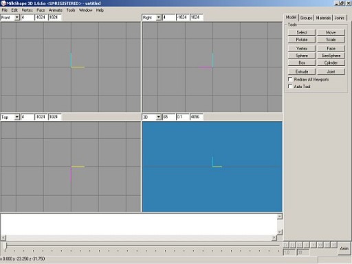
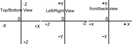
)All right, once you've installed Milkshape, open it up and you should see something like this (You can have different viewports set up):
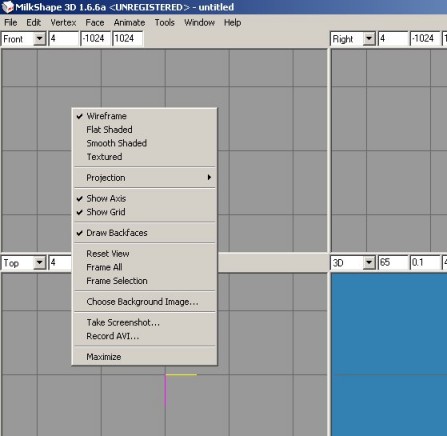
Show Grid, shows the grid... Draw backfaces is rather unimportant at this stage. Reset view will return the view point to its default position ' so if you move the view around, this will return it back home. Frame All will zoom the camera out so you can see all of the model. Frame Selection does the same thing, but zooms out so it can show what parts of the model are selected. Choose background image lets you import an image into the background of the view ' very handy if you have a picture of what you're going to model. Take screenshot lets you save the view into a .bmp file. Record AVI lets you record an animation into an AVI file. And finally, Maximize will maximize that viewport, encompassing all the other viewports. Now onto the 3d view. This is really a viewing viewport'You can't actually modify anything in this view. You can however rotate around your model, to scope out anything that needs fixing/improving
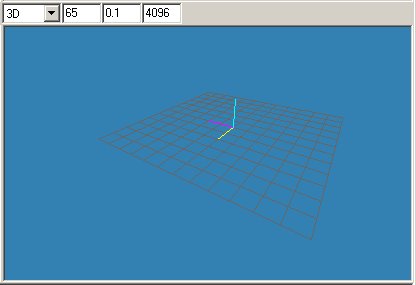
By click and holding the left mouse button, then moving, the camera stays fixed on the center of the viewpoint, but your position rotates and moves. By holding ctrl+left mouse button, you can pan your view or strafe it, by dragging the mouse to the left, right, up or down. By holding shift instead, you can zoom in and out.
Before I speak about actually making a model, I need to define what the different technical terms are and what they mean.
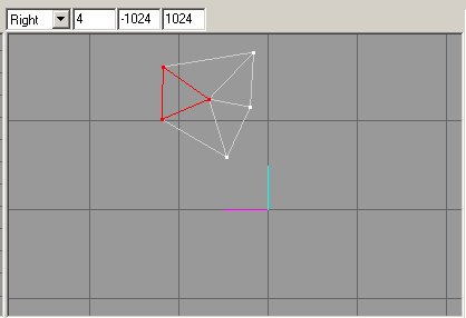
A 'face' is one face or side of an object, it is a triangular, completely flat surface also known as a polygon. It's three corners are shared with the surrounding faces to make surfaces. Here is a picture of a group of 5 faces. The selected one (red) is one face. See how it shares its three dots? These are called 'vertices' You make a face by joining three vertices together. A 'group' is simply a collection of faces grouped together, for convenience for the modeler. When you select one part of a group, the whole group is selected.

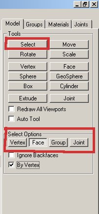
Select Tool
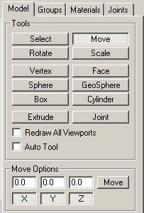
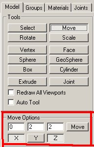
Move Tool
Rotate Tool
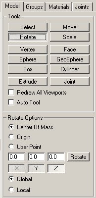
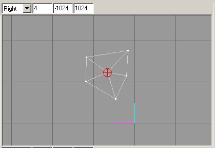
Under the rotation Options, there are three radio buttons. These define what the selected object(s) will rotate or pivot around. Center of Mass means the selected objects will rotate around the center of the selected objects. Origin means the selected objects will rotate or pivot around the axis (those colored lines :p) that are the center of the model. User Point allows the selected objects to rotate around the place where the user clicked when he started to rotate the object.
Global and Local functions only need to be worried about if you are animating an object (If you are animating and the model strangely gets larger, change it to Local setting).
Scale Tool
This can be used when multiple vertices or a face is selected to scale the selection. This means you can shrink or enlarge an object with this. The scale tool can also be used if only one face is selected ' it will just move the 3 vertices closer together.The scale looks exactly the same as the window to the left, bar the Global, Local Functions and is called Scale Options instead of Rotate.
Center of Mass, like in rotating, means the model will be scaled in from the center of the selected object(s). Origin means the model will be scaled in from the center of the void in which the model is (scaled around the axis / three funny colored lines ;). User point means the selected object(s) will be scaled around where you click. Try all these out to get a feel for them.
Vertex and Face Tool
The Face Tool only has one option, which I'll get to later, but the Vertex does not have options, so that's why a pic isn't shown. The Vertex Tool allows you to create a vertex, in turn allowing you to create faces. Each face, as you know, is made up of three vertexes. In modeling, you can't just create faces like you can a cube, or cylinder. First you have to create three vertexes. You can do this by clicking three times anywhere on a 2-D viewport. See those dots come up? Those are vertexes. Now we'll create a face. Click on the Face tool. Now click on the vertices, one at a time. Make sure you click on the vertices in an anti-clockwise direction, or you'll get an invalid face. This won't allow you to compile your model, and it will look weird.Now, if you click on the Face tool, you'll notice it has one option. Threshold. By changing the number of this, you'll change how close you can click to the vertex, to select it when creating a face. So if you have a threshold of 1, you'd have to click directly on the vertex to select it. Have a larger number like 20, and you can click a bit away from it, and it will still be selected for face creation.
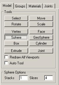
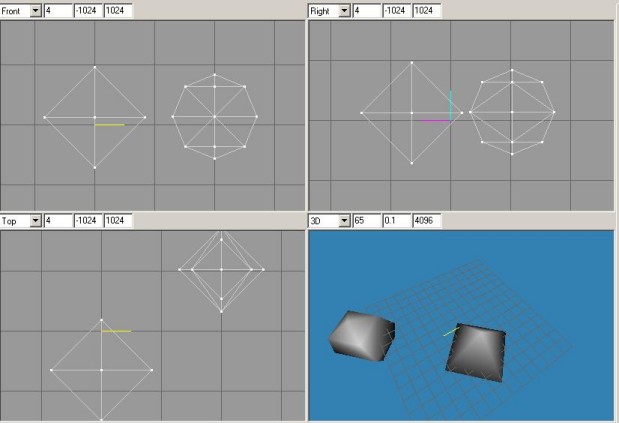
Sphere and Geosphere Tool
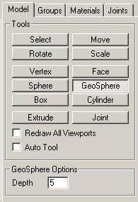
With the Geosphere, the depth option defines how complex the sphere will be, i.e how many polys and how 'curvy' it will be. A depth of 1 is the least complex sphere you can have using the Geosphere tool.
With the Sphere, the Slices is the number of sides it will have. Stacks is how many layers it will have vertically. See below for further explanation:
Box Tool
Not much to this tool. There are no further options. To create a box, select the Box Tool and click then drag in a 2-D Viewport. The new sphere will be created!Cylinder Tool
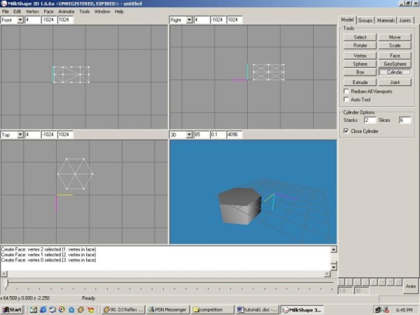
This tool allows you to create a cylinder. There are a few options displayed below, which are easy to remember.Stacks is how many layers will be along a cylinder. You can imagine this like cutting a carrot into rings. Stacks are like this. If you look at the 'Right' Viewport, you can see that the object (cylinder) is two layers or stacks high.
Slices is how many sides there will be to the Cylinder. In the 'Top' Viewport, you can see that the cylinder has 6 sides. The tickbox below those options is 'Close Cylinder' This defines whether or not to create faces on the ends of the cylinder to 'close' it.
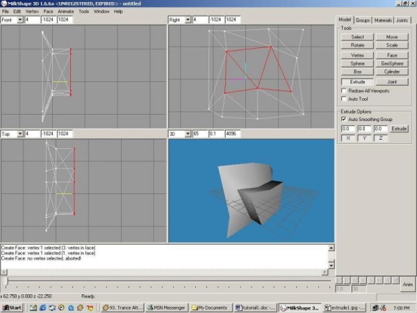
Extrude Tool
This is a complex and very useful tool to have in your disposal. The way it works is that when you have a face, or group of faces selected, you can create the same pattern of face(s) in the direction that you click and drag, with the bridging faces created in between. Here is an example of extruding. In the first, I have selected a group of faces in the middle of some kind of dent.. Then I clicked on extrude. In the 'Right' Viewport, I clicked, and dragged to the right.

Joint Tool
The final tool in the Toolbox is the joint. This is what you use for animating, not getting stoned (well at least in these tuts.. ). The vertices assigned to it, move when it moves .. when you're animating..In any case, it has no extra options, so no piccie included. It works exactly the same as the vertex tool. Click on it, then click on an area in a 2-D viewport. Wallah (sp?) you have a joint. Put that in your pipe and smoke it'(Sorry, enough bad jokes.)
That's all of the Model Tab. With this information in hand, you should be able to start experimenting and making models. I encourage you to go through each tool and see if you can use it! If there are any queries, don't hesitate to direct them to myself. By the way, if you were observant, you would have noticed my winamp in some of the screenies. DJ Reflex and Trance Attack..get into it :cool:.
- Article Credits
- BB – Author
This article was originally published on 69th Vlatitude.
The original URL of the article was http://www.vlatitude.com/tutorials.php?tutID=54.
The archived page is available here.
TWHL only publishes archived articles from defunct websites, or with permission.
For more information on TWHL's archiving efforts, please visit the
TWHL Archiving Project page.
Comments
You must log in to post a comment. You can login or register a new account.