RUST: The BSP Process and Visibility Last edited 2 years ago2022-09-29 07:53:59 UTC
The BSP Process and Visibility
Introduction
This tutorial is written for Quake II and to some extent Quake 3 Arena. However, all Quake engine games work on a similar principle (though not all have hint brushes or detail brushes).The Map
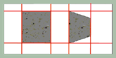
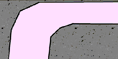
The examples in this tutorial are going to use the following map, which consists of 4 walls, and 2 objects in the middle:
The BSP Process
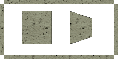
There are 12 extraneous polygons on the outside walls of this map, so let's simplify matters a bit by eliminating them (which will happen anyway during the BSP process if there are no leaks):
During the BSP process qbsp3 takes each polygon one by one and inserts them into the bsp tree. The term tree describes the data structure the bsp nodes are stored in (if the data structure is drawn graphically on a piece of paper, it looks something like a tree or bush). As each polygon is inserted, it will split space up into smaller and smaller regions, but it will only split up the regions it is inserted into. The process is shown graphically below (if this image is not animating, reload the page and don't stop the loading of the page, or open image up in a separate browser window):
In reality, qbsp3 uses certain rules to select which order to insert polygons. First it assigns a really high priority to axial polygons. These are polygons whose X values are all the same, Y values are all the same, or Z values are all the same (in the editor, in 2 of the 3 possible 2d views, the polygon will show as a simple line). After that, it will look for polygons that will split up the remaining uninserted polygons the least. The bsp animation with the darker gray border is the one much more in line with what qbsp3 will actually do. However, for this tutorial, I am going to use the one with the lighter gray border for illustrative purposes.
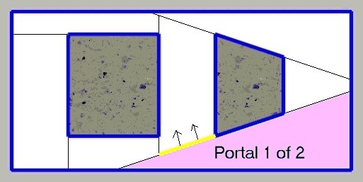
Both the thick blue and thin black lines lie on what are known as bsp split planes. They break the map up into small (or sometimes, not so small) regions. Each of these regions is a bsp node. You will never find a world polygon in the middle of a bsp node. They all lie on a bsp node edge/side. Moving objects, etc. are not part of the bsp tree and are handled separately.
The thick blue lines are your solid polygons. You can't move through them. They are almost always visible. If it is not visible for whatever reason, you will probably wind up with what is known as the Hall Of Mirrors (HOM) effect or see other, further parts of your level through it.
The thin black lines are what become your portals. Portals separate bsp nodes where there is no solid polygon. They are not visible, but polygons generated with a mist-ed brush, or other non solid brush can overlap them. They do not block movement. There are actually 2 between any 2 bsp nodes (where there is no solid polygon). Each of those 2 portals is attached to its respective bsp node. See image below (if this image is not animating, reload the page and don't stop the loading of the page, or open image up in a separate browser window):
When a polygon is inserted that is inside 2 or more bsp nodes, it gets split into several pieces such that each piece is in a single node. However, qbsp3 will later to try to merge faces with identical properties together if possible (so you may have a single polygon attached to multiple bsp nodes), so you often wont see evidence of this effect if you turn on gl_showtris (see discussion of gl_showtris below).
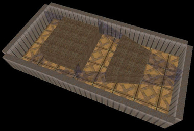
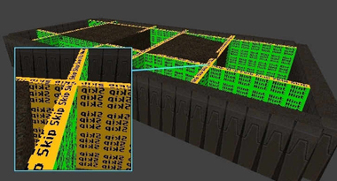
The following is a 3d representation of this map in Quake II:
Visibility Nodes
Lets take the following possible final bsp arrangement (from one of the example bsp-ings above):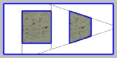
This, by the way, is where the infamous "Leaf portals saw into leaf" warning comes from. When this happens, it means it tried comparing 2 leaf portals that belongs to the same visibility node. There was a nasty bug in the original qbsp3 (yes, qbsp3. It wrote out a bad bsp that qvis3 had problems with) that resulted in seeing this error often. Seeing it often meant that there were serious problems with the map. However, a number of rewritten qbsp3's fixed this problem. Even with fixed qbsp3's, you may still see the warning. Take a look at the following:
There are several other similar situations where you might see this warning, all the result of a computer's finite precision floating point math. If you have a fixed qbsp3, do not worry about this warning.
If the portal in question is axial, this should not happen.
Checking Visibility
So you have your map up and running and want to see how visibility worked out where you have speed problems. The primary way of doing this is using one of the OpenGL rendering modes, then setting gl_showtris 1. Take the following view from base64 (deathmatch compilation of base1, base2, and base3 from the single player game):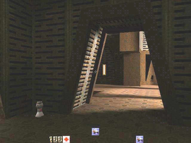

The triangles are not part of the bsp. When polygons are rendered, they get broken up into triangles in the engine.
3Dfx Cards
The 3dfx minidriver does not support gl_showtris. You can use the default OpenGL drivers, but if you are using the software OpenGL (Microsoft's or SGI's), it will be really slow, and possibly somewhat unstable. You can also load the MesaGL driver for 3dfx cards. Once you have the drivers, put it in your Quake II directory (DO NOT put it into your system/system32 directory). Make sure it is named opengl32.dll if it isn't already. Now when you use default opengl drivers, it will use the Mesa drivers (which the above screenshot was taken with).Still Not Seeing Triangles?
If you do not see triangles, you may need to issue the following commands at the console:gl_ext_multitexture 0
vid_restartgl_ext_multitexture 1
vid_restartHint Brushes
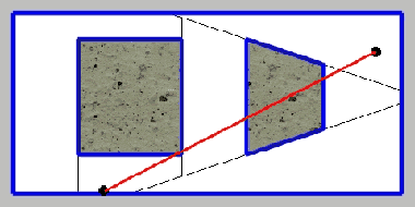
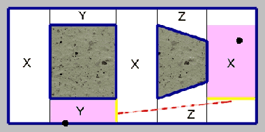
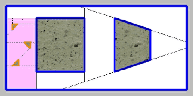
In the example bsp, there are only 4 pairs of bsp nodes that are not visible to each other (shown marked below):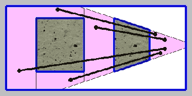
The hint texture is typically used in conjunction with the skip texture. The skip texture polygons are not inserted into the bsp-tree and thus, not used by Quake II. The idea is to take a brush, apply the skip texture, then apply to a single side of the brush the hint texture. This will result in a single hint polygon inserted where the brush is, which is generally all that is necessary. However, you can use an entire hint brush, but this will make the bsp-splits a bit more complicated.
When you lay out your hint planes, you have to place them such that two areas you intend to keep hidden from each other don't have the hint planes facing each other. For the example map, we will try a grid as follows:
These brushes all have 5 skip faces, and 1 hint face. The skip faces are completely ignored, only the hint faces are processed. We could reduce the number of hint/skip brushes down to as few as 3 by using more than one hint face per brush but for this example, we will use 1 hint face per brush (for one thing, by keeping the brushes thin, they don't clutter up the view in the editor as much).
The 2 points we used above are still going to be visible to each other as the new nodes they will be in will still be visible to each other:
It will take some trial and error to get a feel for what works well. Deciding where to place hint planes can be something of an art form. One good use for hint brushes is in hallway bends as follows:
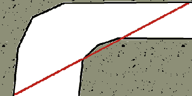
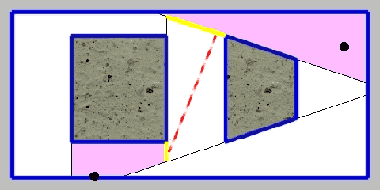
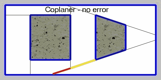
It is possible for portals lying on the same plane to cause problems. We can trust that nodes of the same letter in the above example are not visible to each other in spite of the fact they share portals on the same plane because they are axial, but look at the following 2 nodes: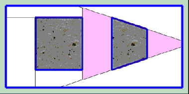 The portals on the planes shared by both shaded nodes are not axial. As a result, slight numerical errors due to the limits of the floating point unit on your CPU may cause them to be visible to each other after all as shown:
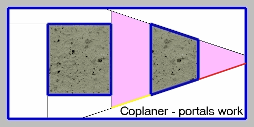 The angle of error shown here is extremely exaggerated. When forcing a split on a non-axial plane, a single hint plane may not be enough. You may want to use a double sided hint brush about 8 or 16 units, with the ideal portal running through the middle as follows:
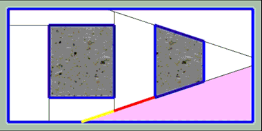
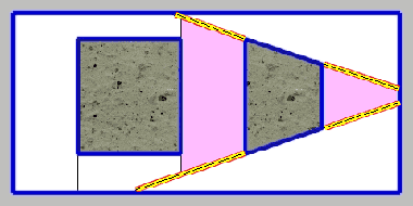 The red/yellow/black striped lines are the hint brushes. The 2 red parts on the edges would be the hint surfaces of the hint brush, the rest of the surfaces of the hint brush would be marked as "skip". The black line running down the center is where the original portal was. This will trap any errors between the two planes. You can use either 2 hint brushes, or opposite sides of the same thin hint brush. This is only necessary when you care about how 2 or more portals that lie on the same plane interact with each other.
Detail Brushes
Lets take our previous map, and add a few small brushes. The final bsp might look something like this: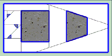
What happens with detail brushes, is that the polygons making it up are inserted into the bsp tree last. Additionally, when detail brush polygons are inserted, they do not create ortals, and the bsp nodes they cut up are treated as one single visibility node. Lets make the 3 triangular brushes detail brushes. Then we will end up with something like:
This can be tricky and will some take some trial and error to get a good feel for. You will want to use gl_showtris mention above as an aid to this process.
Detail Hint Brushes
Detail hint brushes are not part of id's original compiling utilities. If you are using those, you will not be able to use this feature. They were primarily implemented as an aid to terrain generators to keep detail brush based rolling terrain from cutting itself up. Gensurf is capable of using detail hint brushes (it also comes with its own version of qbsp3 that also implements detail hint brushes).Credits
Tutorial written by Geoffrey DeWanMany thanks to those who have helped proofread and give suggestions for this tutorial:
- SmallPileofGibs
- bushboy (for the optimized images)
- some guy I know
- EutecTic
- Johnny Law
- XO (for pdf version)
- Categories
- Archived Articles
- RUST Archive
- Tutorials
- Mapping
- Article Credits
- Geoffrey DeWan – Author
This article was originally published on Gamedesign.net RUST.
The original URL of the article was http://www.gamedesign.net/node/266.
The archived page is available here.
TWHL only publishes archived articles from defunct websites, or with permission.
For more information on TWHL's archiving efforts, please visit the
TWHL Archiving Project page.
Comments
You must log in to post a comment. You can login or register a new account.